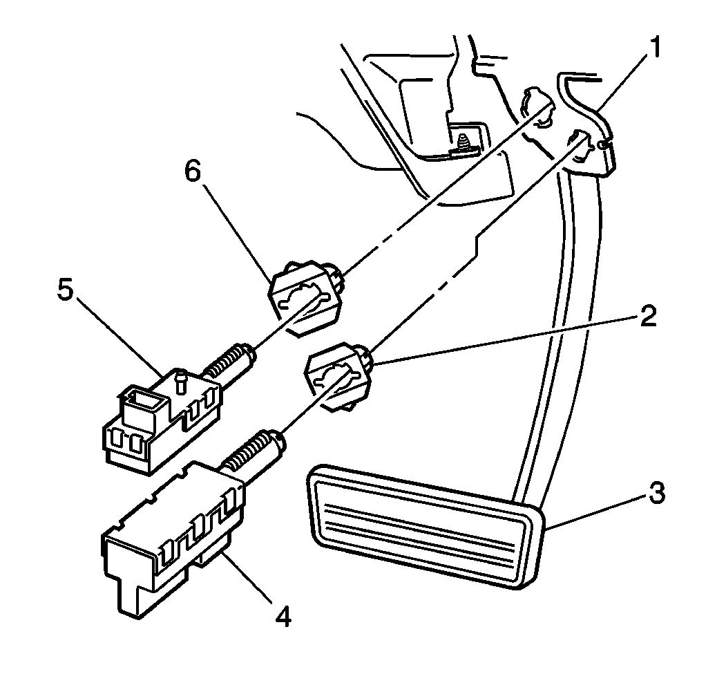
For 1990-2009 cars only
Stop Lamp Switch Replacement Stoplamp
Removal Procedure
Notice: When installing the brake pedal switches it is very important that the brake pedal remain in the full up or at rest position or damage to the brake system and/or switch misadjustment may occur.
- Remove the closeout panel. Refer to Instrument Panel Insulator Panel Replacement - Left Side in Instrument Panel, Gauges and Console.
- Remove the left knee bolster bracket. Refer to Knee Bolster Bracket Replacement in Instrument Panel, Gauges and Console.
- Turn the lower stoplamp switch (4) counter-clockwise and remove.
- Disconnect the stoplamp switch electrical connector.

in Instrument Panel, Gauges and Console.
Installation Procedure
- Connect the lower stoplamp switch electrical connector.
- Install the lower stoplamp switch (4) into the lower retainer (2).
- Turn the stoplamp switch (4) clockwise until it fully locks into position.
- Install the left knee bolster bracket. Refer to Knee Bolster Bracket Replacement in Instrument Panel, Gauges and Console.
- Install the left closeout panel. Refer to Instrument Panel Insulator Panel Replacement - Left Side in Instrument Panel, Gauges and Console.

Stop Lamp Switch Replacement ABS/TCC
Removal Procedure
Notice: When installing the brake pedal switches it is very important that the brake pedal remain in the full up or at rest position or damage to the brake system and/or switch misadjustment may occur.
- Remove the left knee bolster bracket. Refer to Knee Bolster Bracket Replacement in Instrument Panel, Gauges and Console.
- Remove the closeout panel. Refer to Instrument Panel Insulator Panel Replacement - Left Side in Instrument Panel, Gauges and Console.
- Disconnect the upper stoplamp switch electrical connector.

Turn the upper stoplamp switch (5) counter-clockwise and remove.
Installation Procedure
- Connect the upper stoplamp switch electrical connector.
- Install the upper stoplamp switch (5) into the upper retainer (6).
- Turn the stoplamp switch (5) clockwise until it fully locks into position.
- Install the closeout panel. Refer to Instrument Panel Insulator Panel Replacement - Left Side in Instrument Panel, Gauges and Console.
- Install the left knee bolster bracket. Refer to Knee Bolster Bracket Replacement in Instrument Panel, Gauges and Console.

