DTC C1287 Steering Sensor Rate Malfunction w/JL4
Circuit Description
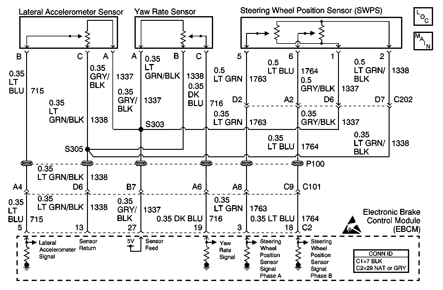
The steering wheel position sensor supplies 2 analog inputs, Phase A and Phase B, to the EBCM. The 2 input signals are approximately 90 degrees out of phase. By interpreting the relationship between the 2 inputs, the EBCM can determine the position of the steering wheel and the direction of steering wheel rotation.
Steer angle centering is the process by which the EBCM calibrates the steering sensor output so that the output reads zero when the steering wheel is centered. Using the yaw rate input, lateral accelerometer input, and wheel speed sensor inputs, the initial steering center position is calculated after driving greater than 10 km/h (6 mph) for more than 10 seconds in a straight line on a level surface.
Conditions for Running the DTC
The ignition is ON.
Conditions for Setting the DTC
One of the following conditions occur:
| • | The steering wheel position sensor is synchronized and the steer rate (speed that the steering wheel appears to be turning) is greater than 1100 degrees/second. |
| • | The steer rate is less than 10 degrees/second and the difference in the phase angle between Phase A and Phase B is greater than 20 degrees. |
| • | The 2 steering sensor signals (Phase A and Phase B) do not agree for 1 second. Under this condition, this DTC will set along with DTC C1281. |
Action Taken When the DTC Sets
| • | The EBCM disables the VSES for the duration of the ignition cycle. |
| • | The DIC displays the SERVICE STABILITY SYSTEM message. |
| • | The ABS/TCS remains functional. |
Conditions for Clearing the DTC
| • | The condition for the DTC is no longer present and the DTC is cleared with a scan tool. |
| • | The electronic brake control module (EBCM) automatically clears the history DTC when a current DTC is not detected in 100 consecutive drive cycles. |
Diagnostic Aids
| • | During diagnosis, park the vehicle on a level surface. |
| • | Check the vehicle for proper alignment. The car should not pull in either direction while driving straight on a level surface. |
| • | Find out from the driver under what conditions the DTC was set (when the DIC displayed the SERVICE STABILITY SYSTEM message). This information will help to duplicate the failure. |
| • | The Snapshot function on the scan tool can help find an intermittent DTC. |
Test Description
The number below refers to the step number on the diagnostic table.
-
This step performs the Steering Position Sensor Test to see if the steering wheel position sensor (SWPS) is operating properly.
-
Tests for the proper operation of the Phase A circuit in the low voltage range.
-
Tests for the proper operation of the Phase B circuit in the low voltage range.
-
Tests for the proper operation of the Phase A circuit in the high voltage range. If the fuse in the jumper opens when you perform this test, the signal circuit is shorted to ground.
-
Tests for the proper operation of the Phase B circuit in the high voltage range. If the fuse in the jumper opens when you perform this test, the signal circuit is shorted to ground.
-
Tests for a short to voltage in the 5 volt reference circuit.
-
Tests for a high resistance or an open in the ground circuit.
Step | Action | Value(s) | Yes | No | ||||||
|---|---|---|---|---|---|---|---|---|---|---|
1 | Did you perform the ABS Diagnostic System Check? | -- | Go to Step 2 | |||||||
Did the steering wheel position sensor (SWPS) pass the test? | -- | Go to Diagnostic Aids | ||||||||
Does the scan tool indicate the Dual Analog SWPS Input A parameter is less than the specified value? | 0.15 V | |||||||||
With the scan tool, observe the Dual Analog SWPS Input B parameter. Does the scan tool indicate the Dual Analog SWPS Input B parameter is less than the specified value? | 0.15 V | |||||||||
Does the scan tool indicate that the Dual Analog SWPS Input A parameter is greater than the specified value? | 4.85 V | |||||||||
Does the scan tool indicate that the Dual Analog SWPS Input B parameter is greater than the specified value? | 4.85 V | |||||||||
Does the voltage measure less the specified value? | 5 V | |||||||||
Does the resistance measure less than the specified value? | 5 ohms | |||||||||
9 | Test the 5 volt reference circuit of the steering wheel position sensor (SWPS) for a short to voltage. Refer to Circuit Testing and Wiring Repairs in Wiring Systems. Did you find and correct the condition? | -- | ||||||||
10 | Test the 5 volt reference circuit of the steering wheel position sensor (SWPS) for the following conditions:
Refer to Circuit Testing and Wiring Repairs in Wiring Systems. Did you find and correct the condition? | -- | ||||||||
11 | Test the Phase A signal circuit of the steering wheel position sensor (SWPS) for the following conditions:
Refer to Circuit Testing and Wiring Repairs in Wiring Systems. Did you find and correct the condition? | -- | ||||||||
12 | Test the Phase B signal circuit of the steering wheel position sensor (SWPS) for the following conditions:
Refer to Circuit Testing and Wiring Repairs in Wiring Systems. Did you find and correct the condition? | -- | ||||||||
13 | Test the Phase A signal circuit of the steering wheel position sensor (SWPS) for a short to voltage. Refer to Circuit Testing and Wiring Repairs in Wiring Systems. Did you find and correct the condition? | -- | ||||||||
14 | Test the Phase B signal circuit of the steering wheel position sensor (SWPS) for a short to voltage. Refer to Circuit Testing and Wiring Repairs in Wiring Systems. Did you find and correct the condition? | -- | ||||||||
15 |
Important: Removing battery voltage or ground from the EBCM will result in the
following conditions:
Did you find and correct the condition? | -- | ||||||||
16 | Inspect for poor connections at the harness connector of the steering wheel position sensor (SWPS). Refer to Testing for Intermittent Conditions and Poor Connections and Connector Repairs in Wiring Systems. Did you find and correct the condition? | -- | ||||||||
17 | Inspect for poor connections at the harness connector of the EBCM. Refer to Testing for Intermittent Conditions and Poor Connections and Connector Repairs in Wiring Systems. Did you find and correct the condition? | -- | ||||||||
18 | Replace the steering wheel position sensor (SWPS). Refer to Steering Shaft, Lower Bearing, and Jacket - Disassemble - Off Vehicle and Steering Shaft, Lower Bearing, and Jacket - Assemble - Off Vehicle in Steering Wheel and Column - Tilt. Did you complete the replacement? | -- | -- | |||||||
19 |
Important: Perform the setup procedure for the EBCM. An unprogrammed EBCM will
result in the following conditions:
Replace the EBCM. Refer to Electronic Brake Control Module Replacement . Did you complete the replacement? | -- | -- | |||||||
20 |
Does the DTC reset? | -- | System OK |
