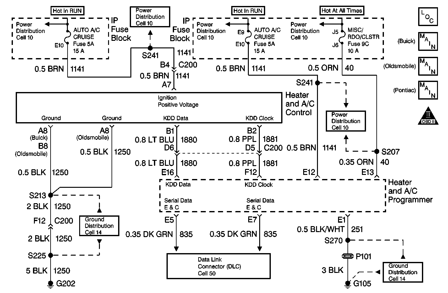
Circuit Description
The HVAC control assembly sends input data through circuit 1880 to the HVAC programmer. The HVAC programmer uses this data to control the actuators on the HVAC module assembly.
Conditions for Setting the DTC
| • | The ignition is on. |
| • | A circuit is open or shorted. |
Action Taken When the DTC Sets
Code 035 is set.
Conditions for Clearing the DTC
| • | Using a Scan Tool . |
| • | A history DTC will clear when 40 consecutive ignition cycles occurred without a malfunction. |
| • | HVAC programmer battery voltage is interrupted. |
Test Description
Step | Action | Value(s) | Yes | No |
|---|---|---|---|---|
1 |
Install a jumper between HVAC control assembly terminal B1 and terminal B2. Does DTC 35 change status from CURRENT to HISTORY as displayed on the Scan Tool ? | -- | Go to Step 3 | Go to Step 2 |
2 |
Refer to Measuring Voltage in Wiring Systems. Does the voltage approximately equal the specified value? | 8 V | Go to Step 4 | Go to Step 5 |
3 | Replace the HVAC control assembly. Refer to Control Assembly Replacement . Is the repair complete? | -- | System OK | -- |
4 |
Refer to Probing Electrical Connectors in Wiring Systems. Does the voltage approximately equal the specified value? | 3.5 V | Go to Step 8 | Go to Step 9 |
Backprobe terminal F12 and terminal E1 of the HVAC programmer harness connector. Refer to Probing Electrical Connectors in Wiring Systems. Does the voltage approximately equal the specified value? | 8 V | Go to Step 6 | Go to Step 7 | |
6 | Repair the open in CKT 1881. Refer to Wiring Repairs in Wiring Systems. Is the repair complete? | -- | System OK | -- |
7 |
Refer to Intermittents and Poor Connections Diagnosis in Wiring Systems. Is the repair complete? | -- | System OK | -- |
8 | Backprobe the HVAC programmer harness connector terminal E16 and terminal E1. Refer to Probing Electrical Connectors in Wiring Systems. Does the voltage approximately equal the specified value? | 3.5 V | Go to Step 10 | Go to Step 11 |
9 |
Is the repair complete? | -- | System OK | -- |
10 |
Is the repair complete? | -- | System OK | -- |
11 | Repair the open in CKT 1880. Refer to Wiring Repairs in Wiring Systems. Is the repair complete? | -- | System OK | -- |
