DTC P0713 Transmission Fluid Temperature (TFT) Sensor Circuit High Input Buick Built Before 6/17/96
Circuit Description
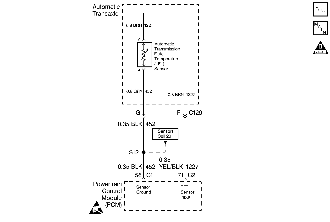
The Automatic Transmission Fluid Temperature (TFT) sensor is a negative coefficient thermistor. The sensor resistance changes with temperature. The Powertrain Control Module (PCM) provides a 5-volt reference to the sensor on circuit 1227. An open in circuit 1227 or circuit 452 results in high signal voltage. The TFT operating range is from -40 to +151°C (-40 to +304°F).
If the PCM detects a voltage input greater than 4.92 volts in the TFT Sensor circuit, then DTC P0713 sets. DTC P0713 is a type A DTC.
Conditions for Setting the DTC
| • | The system voltage is 10-16 volts. |
| • | The ignition is ON. |
| • | The PCM detects a TFT Sensor voltage of 4.92 volts or more for 7 minutes. |
Action Taken When the DTC Sets
| • | The default TFT is 131°C (268°F). |
| • | The PCM illuminates the Malfunction Indicator Lamp (MIL). |
Conditions for Clearing the MIL/DTC
| • | The PCM turns OFF the MIL after three consecutive ignition cycles without a failure reported. |
| • | A scan tool can clear the DTC from the PCM history. The PCM clears the DTC from the PCM history if the vehicle completes 40 warm-up cycles without a failure reported. |
| • | The PCM cancels the DTC default actions when the fault no longer exists and the ignition is OFF long enough in order to power down the PCM. |
Diagnostic Aids
| • | Inspect the wiring for poor electrical connections at the PCM. Inspect the wiring at the transmission 7-way connector. Look for the following problems: |
| - | A bent terminal |
| - | A backed out terminal |
| - | A damaged terminal |
| - | Poor terminal tension |
| - | A chafed wire |
| - | A broken wire inside the insulation |
| • | When diagnosing for an intermittent short or open, massage the wiring harness while watching the test equipment for a change. |
| • | Refer to Temperature vs Resistance . |
Test Description
The numbers below refer to the step numbers on the diagnostic chart.
-
A scan tool Trans. Fluid Temp. of -36°C (-33°F) or less indicates that this DTC is current.
-
This Step isolates the fault between the transmission harness or the engine harness.
Step | Action | Value(s) | Yes | No | ||||
|---|---|---|---|---|---|---|---|---|
1 | Was the Powertrain On-Board Diagnostic (OBD) System Check performed? | -- | ||||||
2 | Perform the transmission fluid checking procedure. Refer to Transmission Fluid Check . Have you performed the procedure? | -- | Go to Transmission Fluid Check | |||||
Important: Before clearing the DTCs, use the scan tool in order to record the Failure Records for reference. Using the Clear Info function will erase the stored Failure Records from the PCM. Does the scan tool display an Automatic Transmission Fluid Temperature (TFT) less than the specified value? | -36°C (-33°F) | Go to Diagnostic Aids | ||||||
Important: If the ignition is ON for more than 5 minutes, the PCM uses the default transmission temperature. Does the scan tool display a TFT greater than the specified value? | 145°C (293°F) | |||||||
5 | Connect circuit 1227, terminal F to a known good ground. Does the scan tool display a TFT greater than the specified value? | 145°C (293°F) | ||||||
6 | Inspect circuit 1227 of the engine harness for an open. Refer to Troubleshooting Procedures, Section 8. Did you find and correct a problem? | -- | ||||||
7 | Inspect circuit 452 of the engine harness for an open. Refer to Troubleshooting Procedures, Section 8. Did you find and correct a problem? | -- | ||||||
8 | Inspect transmission circuits 1227 and 452 for an open. Refer to Troubleshooting Procedures, Section 8. Did you find and correct a problem? | -- | ||||||
9 | Replace the TFT Sensor. Refer to Solenoids and Wiring Harness, in On-Vehicle Service. Is the replacement complete? | -- | -- | |||||
10 | Replace the PCM. Refer to Powertrain Control Module Replacement/Programming , Section 6. Is the replacement complete? | -- | -- | |||||
11 | In order to verify your repair, perform the following procedure:
Has the test run and passed? | -- | System OK |
DTC P0713 Transmission Fluid Temperature (TFT) Sensor Circuit High Input All Other Applications
Circuit Description
The Automatic Transmission Fluid Temperature (TFT) sensor is a negative coefficient thermistor. The sensor resistance changes with temperature. The Powertrain Control Module (PCM) provides a 5-volt reference to the sensor on circuit 1227. An open in circuit 1227 or circuit 452 results in high signal voltage. The TFT operating range is from -40 to +151°C (-40 to +304°F).
If the PCM detects a voltage input greater than 4.92 volts in the TFT Sensor circuit, then DTC P0713 sets. DTC P0713 is a type D DTC.
Conditions for Setting the DTC
| • | The system voltage is 10-16 volts. |
| • | The ignition is ON. |
| • | The PCM detects a TFT Sensor voltage of 4.92 volts or more for 7 minutes. |
Action Taken When the DTC Sets
| • | If the Engine Run Time is less than 3 minutes and: |
| - | Intake Air Temperature (IAT) DTC P0112, P0113, P1111, or P1112 is set, then the default Automatic Transmission Fluid Temperature (TFT) is 0°C (32°F). |
| - | No IAT DTC is set, then the default TFT is set to the IAT saved at start up. |
| • | If the engine run time is greater than 3 minutes and Engine Coolant Temperature (ECT) DTC P0117, P0118, P1114, or P1115 is set, then the default TFT is 131°C (268°F). |
| • | If the engine run time is greater than 3 minutes, no ECT DTC is set, and: |
| - | The ECT is less than 45°C (113°F), then the default TFT is 12°C (54°F). |
| - | The ECT is greater than 115°C (239°F), then the default TFT is 131°C (268°F). |
| - | The ECT is 45-115°C (113-239°F) and: |
| • | The IAT DTC P0112, P0113, P1111, or P1112 is set, then the default TFT is set to equal the ECT. |
| • | The IAT at start up is less than 0°C (32°F), then the default TFT is set to ECT minus 10°C (18°F). |
| • | The IAT at start up is greater than 28°C (82°F), then the default TFT is set to ECT plus 10°C (18°F). |
| • | The IAT at start up is 0-28°C (32-82°F), then the default TFT is set to equal ECT. |
| - | The PCM does not turn on the Malfunction Indicator Lamp (MIL). |
| - | The PCM disables shift adapts. |
Conditions for Clearing the DTC
| • | A scan tool can clear the DTC from the PCM history. The PCM clears the DTC from the PCM history if the vehicle completes 40 warm-up cycles without a failure reported. |
| • | The PCM cancels the DTC default actions when the fault no longer exists and the ignition is OFF long enough in order to power down the PCM. |
Diagnostic Aids
| • | Inspect the wiring for poor electrical connections at the PCM. Inspect the wiring at the transmission 7-way connector. Look for the following problems: |
| - | A bent terminal |
| - | A backed out terminal |
| - | A damaged terminal |
| - | Poor terminal tension |
| - | A chafed wire |
| - | A broken wire inside the insulation |
| • | When diagnosing for an intermittent short or open, massage the wiring harness while watching the test equipment for a change. |
| • | Refer to Temperature vs Resistance . |
Test Description
The numbers below refer to the step numbers on the diagnostic chart.
-
A scan tool Trans. Fluid Temp. of -36°C (-33°F) or less indicates that this DTC is current.
-
This Step isolates the fault between the transmission harness or the engine harness.
Step | Action | Value(s) | Yes | No | ||||
|---|---|---|---|---|---|---|---|---|
1 | Was the Powertrain On-Board Diagnostic (OBD) System Check performed? | -- | ||||||
2 | Perform the transmission fluid checking procedure. Refer to Transmission Fluid Check . Have you performed the procedure? | -- | Go to Transmission Fluid Check | |||||
Important: Before clearing the DTCs, use the scan tool in order to record the Failure Records for reference. Using the Clear Info function will erase the stored Failure Records from the PCM. Does the scan tool display an Automatic Transmission Fluid Temperature (TFT) less than the specified value? | -36°C (-33°F) | Go to Diagnostic Aids | ||||||
Important: If the ignition is ON for more than 5 minutes, the PCM uses the default transmission temperature. Does the scan tool display a TFT greater than the specified value? | 145°C (293°F) | |||||||
5 | Connect circuit 1227, terminal F to a known good ground. Does the scan tool display a TFT greater than the specified value? | 145°C (293°F) | ||||||
6 | Inspect circuit 1227 of the engine harness for an open. Refer to Troubleshooting Procedures, Section 8. Did you find and correct a problem? | -- | ||||||
7 | Inspect circuit 452 of the engine harness for an open. Refer to Troubleshooting Procedures, Section 8. Did you find and correct a problem? | -- | ||||||
8 | Inspect transmission circuits 1227 and 452 for an open. Refer to Troubleshooting Procedures, Section 8. Did you find and correct a problem? | -- | ||||||
9 | Replace the TFT Sensor. Refer to Solenoids and Wiring Harness, in On-Vehicle Service. Is the replacement complete? | -- | -- | |||||
10 | Replace the PCM. Refer to Powertrain Control Module Replacement/Programming , Section 6. Is the replacement complete? | -- | -- | |||||
11 | In order to verify your repair, perform the following procedure:
Has the test run and passed? | -- | System OK |
