Power Vacuum Brake Booster Replacement LS4
Special Tools
J 22805-B Brake Booster Holder
Removal Procedure
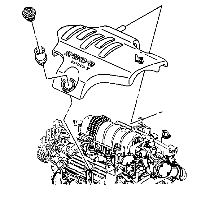
- Remove the upper intake manifold sight shield. Refer to Upper Intake Manifold Sight Shield Replacement.
- Remove the air cleaner assembly. Refer to Air Cleaner Assembly Replacement.
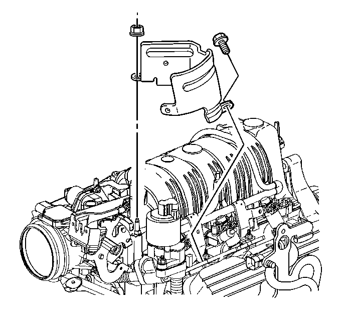
- Remove the brake pressure modulator valve (BPMV) bracket. Refer to Brake Pressure Modulator Valve Bracket Replacement.
- Remove the exhaust crossover pipe. Refer to Exhaust Crossover Pipe Replacement.
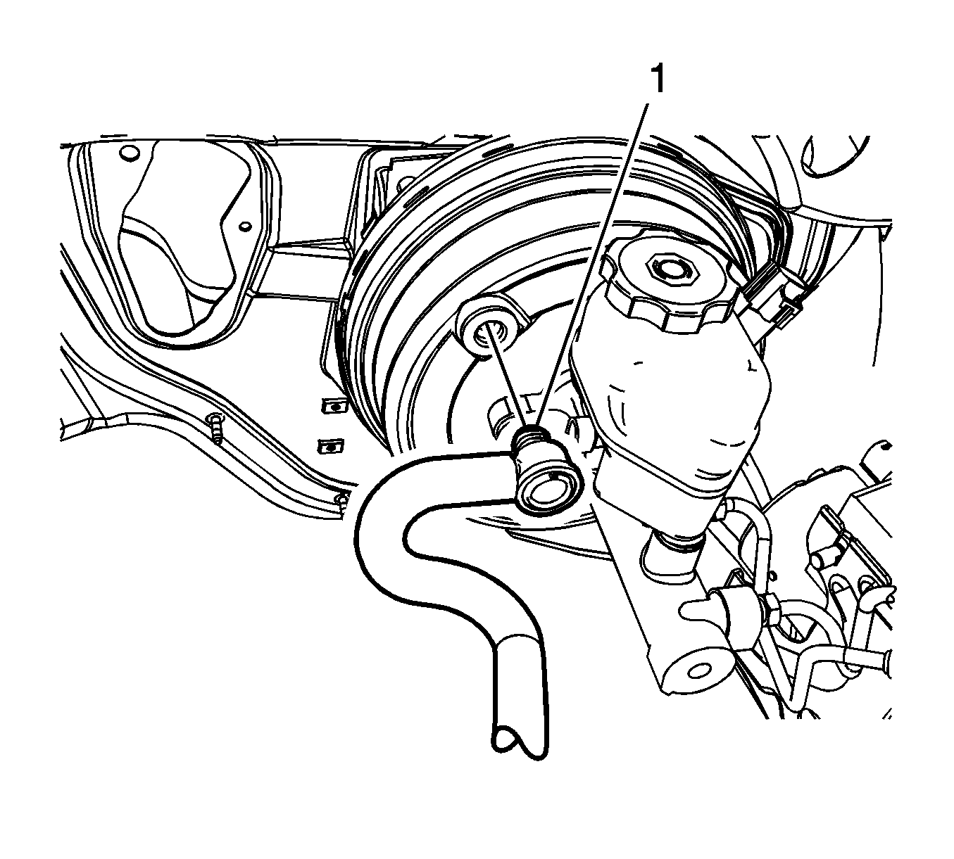
- Disconnect the vacuum power brake booster check valve and hose assembly (1).
- Disconnect the vacuum power brake booster vacuum sensor electrical connector.
- Remove the left side instrument panel insulator panel. Refer to Instrument Panel Insulator Panel Replacement - Left Side.
- Remove the vacuum power brake booster pushrod nut (1).
- Remove the vacuum power brake booster pushrod bushing (1).
- Remove the vacuum power brake pushrod (1) from the brake pedal pin.
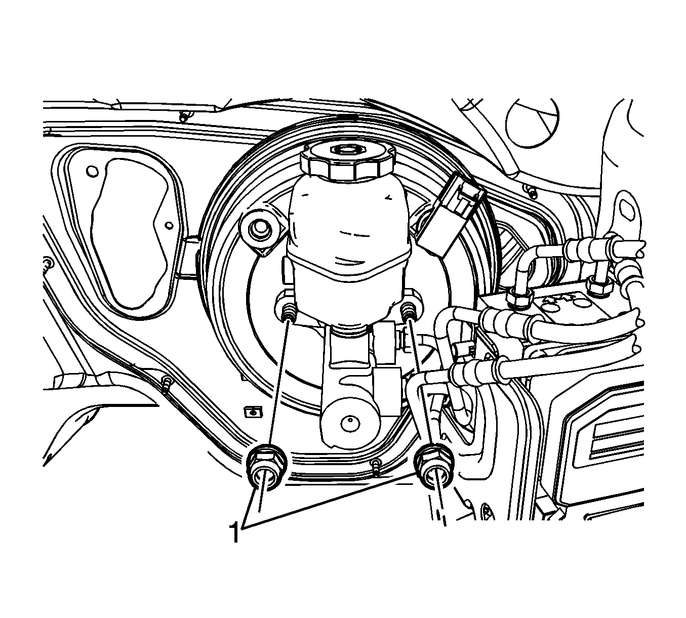
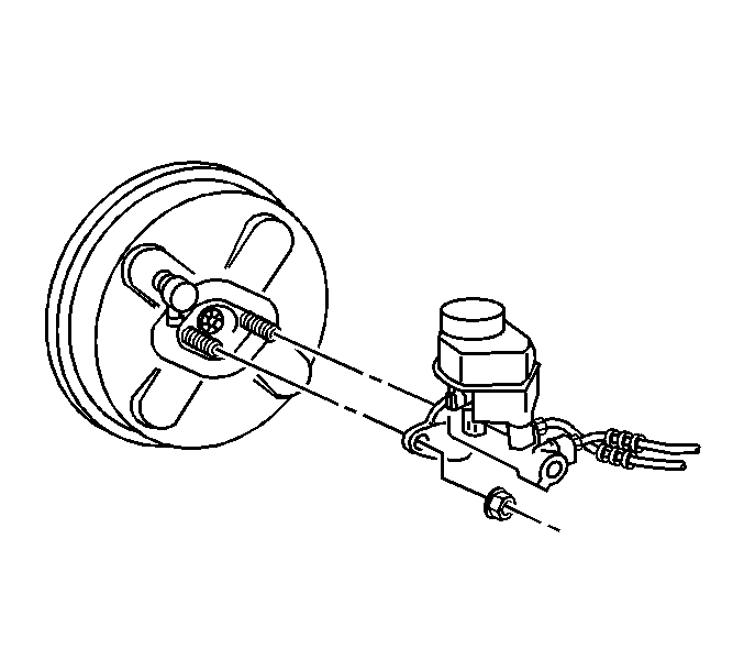
- Remove the master cylinder nuts (1).
- Without disconnecting the brake pipes, remove and position aside the brake master cylinder.
- Install the J 22805-B to the vacuum power brake booster and secure with the master cylinder nuts.
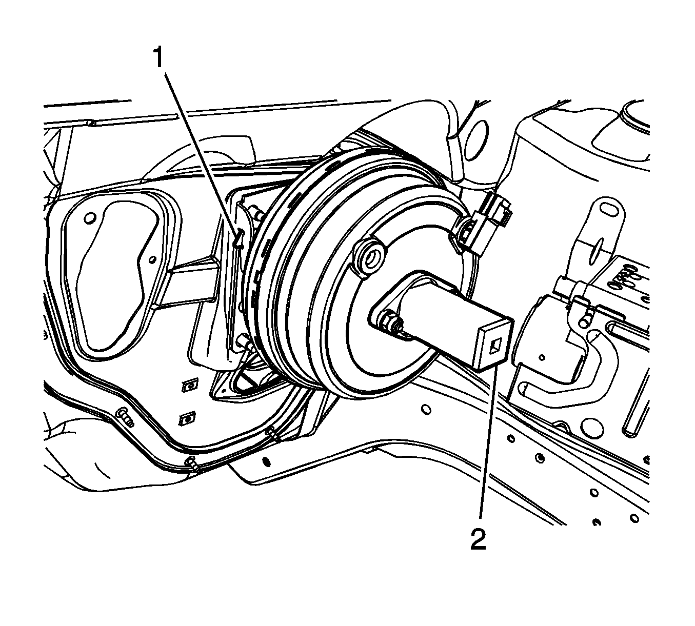
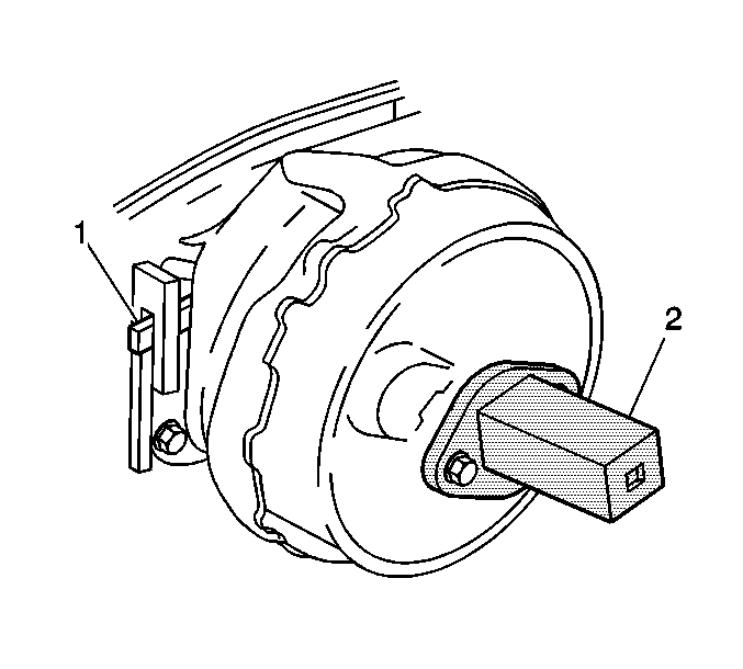
- Press the vacuum power brake booster locking tab (1) while rotating the J 22805-B (2) counter clockwise.
- Remove the vacuum power brake booster.
Secure the master cylinder with heavy mechanics wire or equivalent.
Installation Procedure
- Install the vacuum power brake booster.
- Press the vacuum power brake booster locking tab (1) while rotating the J 22805-B (2) clockwise.
- Remove the J 22805-B from the vacuum power brake booster and discard the master cylinder nuts.
- Install the master cylinder to the vacuum power brake booster.
- Install new master cylinder nuts (1).
- Install the vacuum power brake pushrod (1) to the brake pedal pin.
- Install the vacuum power brake booster pushrod bushing (1).
- Install the vacuum power brake booster pushrod nut (1).
- Install the left side instrument panel insulator panel. Refer to Instrument Panel Insulator Panel Replacement - Left Side.
- Connect the vacuum power brake booster check valve and hose assembly (1).
- Connect the vacuum power brake booster vacuum sensor electrical connector.
- Install the exhaust crossover pipe. Refer to Exhaust Crossover Pipe Replacement.
- Install the BPMV bracket. Refer to Brake Pressure Modulator Valve Bracket Replacement.
- Install the air cleaner assembly. Refer to Air Cleaner Assembly Replacement.
- Install the upper intake manifold sight shield. Refer to Upper Intake Manifold Sight Shield Replacement.
Ensure the locking tab is fully engaged in the vacuum brake booster mounting plate.
Notice: Refer to Fastener Notice in the Preface section.
Tighten
Tighten the nuts to 33 N·m (24 lb ft).
Tighten
Tighten the nut to 13 N·m (115 lb in).
Power Vacuum Brake Booster Replacement LY7
Special Tools
J 22805-B Power Brake Booster Holder
Removal Procedure
Caution: When replacing the power booster brake, make sure that the cruise control cable is not routed between the booster and the cowl. If the cable is damaged or pinched, it must be replaced. Failure to do this could result in personal injury.
- Disconnect the negative battery cable. Refer to Battery Negative Cable Disconnection and Connection .
- Remove the left instrument panel insulator panel. Refer to Instrument Panel Insulator Panel Replacement - Left Side .
- Remove the brake pedal position sensor. Refer to Brake Pedal Position Sensor Replacement .
- Remove the vacuum power brake booster pushrod nut (1).
- Remove the brake pedal pushrod bushing (1).
- Disconnect the vacuum power brake booster pushrod (1) from the brake pedal.
- Drain the cooling system. Refer to Cooling System Draining and Filling .
- Remove the coolant heater pipes from the engine.
- Disconnect the brake fluid level sensor electrical connector from the master cylinder reservoir.
- Remove the 2 master cylinder nuts.
- Without disconnecting the brake pipes, remove and position aside the master cylinder.
- Secure the master cylinder with heavy mechanics wire or equivalent.
- Remove and position aside the vacuum power brake booster check valve and vacuum hose assembly.
- Remove the exhaust crossover pipe. Refer to Exhaust Crossover Pipe Replacement .
- Remove the brake pressure modulator valve (BPMV) bracket. Refer to Brake Pressure Modulator Valve Bracket Replacement .
- Install the J 22805-B to the vacuum power brake booster.
- While pressing the locking tab (1), rotate the vacuum power brake booster counterclockwise by using a suitable tool on the J 22805-B .
- Remove the vacuum power brake booster.
- Remove the J 22805-B from the vacuum power brake booster.
Installation Procedure
Notice: Internal components of this booster are not serviceable. The housing must not be unstaked and separated. Separating the housing will cause permanent deformation, preventing the booster from holding proper volume.
Notice: Inspect the locking flanges on booster and mounting plate. Replace the booster and mounting plate if the locking flanges are bent or damaged.
- Install the vacuum power brake booster to the vehicle.
- Rotate the vacuum power brake booster clockwise until the locking tab (1) engages the flange.
- Remove the J 22805-B (2) from the vacuum power brake booster.
- Install the BPMV bracket. Refer to Brake Pressure Modulator Valve Bracket Replacement .
- Install the master cylinder.
- Install the master cylinder nuts.
- Install the vacuum power brake booster check valve and hose assembly.
- Connect the brake fluid level sensor electrical connector.
- Install the exhaust crossover pipe. Refer to Exhaust Crossover Pipe Replacement .
- Install the coolant heater pipes to the engine.
- Fill the cooling system. Refer to Cooling System Draining and Filling .
- Connect the vacuum power brake pushrod (1) to the brake pedal.
- Install the brake pedal pushrod bushing (1).
- Install the vacuum power brake booster pushrod nut (1).
- Install the brake pedal position sensor. Refer to Brake Pedal Position Sensor Replacement .
- Install the left instrument panel insulator panel. Refer to Instrument Panel Insulator Panel Replacement - Left Side .
- Connect the negative battery cable. Refer to Battery Negative Cable Disconnection and Connection .
Important: Ensure the locking tab is fully engaged in the locking flange.
Notice: Refer to Fastener Notice in the Preface section.
Tighten
Tighten the nuts to 33 N·m (24 lb ft).
Tighten
Tighten the nut to 13 N·m (115 lb in).
Power Vacuum Brake Booster Replacement L26
Special Tools
J 22805-B Power Brake Booster Holder
Removal Procedure
- Disconnect the negative battery cable. Refer to Battery Negative Cable Disconnection and Connection.
- Remove the left instrument panel insulator panel. Refer to Instrument Panel Insulator Panel Replacement - Left Side.
- Remove the brake pedal position sensor. Refer to Brake Pedal Position Sensor Replacement.
- Remove the vacuum power brake booster pushrod nut (1).
- Remove the brake pedal pushrod bushing (1).
- Disconnect the vacuum power brake booster pushrod (1) from the brake pedal.
- Remove the fuel injector sight shield. Refer to Fuel Injector Sight Shield Replacement.
- Disconnect the brake fluid level sensor electrical connector from the master cylinder reservoir.
- Remove the 2 master cylinder nuts.
- Without disconnecting the brake pipes, remove and position aside the master cylinder.
- Secure the master cylinder with heavy mechanics wire or equivalent.
- Remove and position aside the vacuum power brake booster check valve and vacuum hose assembly.
- Rotate the engine forward for service access. Refer to Rotating the Engine for Service Access.
- Remove the nut, bolt, and the EGR valve wiring harness heat shield.
- Remove the transmission fluid filler tube and position aside. Refer to Transmission Fluid Filler Tube Replacement.
- Remove the brake pressure modulator valve (BPMV) bracket. Refer to Brake Pressure Modulator Valve Bracket Replacement.
- Install the J 22805-B to the vacuum power brake booster.
- While pressing the locking tab (1), rotate the vacuum power brake booster counterclockwise by using a suitable tool on the J 22805-B .
- Remove the vacuum power brake booster.
- Remove the J 22805-B from the vacuum power brake booster.
Installation Procedure
Notice: Internal components of this booster are not serviceable. The housing must not be unstaked and separated. Separating the housing will cause permanent deformation, preventing the booster from holding proper volume.
Notice: Inspect the locking flanges on booster and mounting plate. Replace the booster and mounting plate if the locking flanges are bent or damaged.
- Install the vacuum power brake booster to the vehicle.
- Rotate the vacuum power brake booster clockwise until the locking tab (1) engages the flange.
- Remove the J 22805-B (2) from the vacuum power brake booster.
- Install the BPMV bracket. Refer to Brake Pressure Modulator Valve Bracket Replacement.
- Install the EGR valve wiring harness heat shield.
- Install the EGR wiring harness heat shield bolt and nut.
- Install the transmission fluid filler tube bracket. Refer to Transmission Fluid Filler Tube Replacement.
- Rotate the engine to the installed position. Refer to Rotating the Engine for Service Access.
- Install the vacuum power brake booster check valve and hose assembly.
- Install the master cylinder.
- Install the master cylinder nuts.
- Connect the brake fluid level sensor electrical connector.
- Install the fuel injector sight shield. Refer to Fuel Injector Sight Shield Replacement.
- Connect the vacuum power brake pushrod (1) to the brake pedal.
- Install the brake pedal pushrod bushing (1).
- Install the vacuum power brake booster pushrod nut (1).
- Install the brake pedal position sensor. Refer to Brake Pedal Position Sensor Replacement.
- Install the left instrument panel insulator panel. Refer to Instrument Panel Insulator Panel Replacement - Left Side.
- Connect the negative battery cable. Refer to Battery Negative Cable Disconnection and Connection.
Important: Ensure the locking tab is fully engaged in the locking flange.
Notice: Refer to Fastener Notice in the Preface section.
Tighten
Tighten the bolt and nut to 10 N·m (89 lb in).
Tighten
Tighten the nuts to 33 N·m (24 lb ft).
Tighten
Tighten the nut to 13 N·m (115 lb in).
