For 1990-2009 cars only
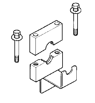
Special Tools
| • | J 35910 Drive Axle Seal Clamp Pliers |
| • | J 8059 Snap Ring Pliers |
| • | J 41048 Drive Axle Swage Ring Clamp |
Disassemble Procedure
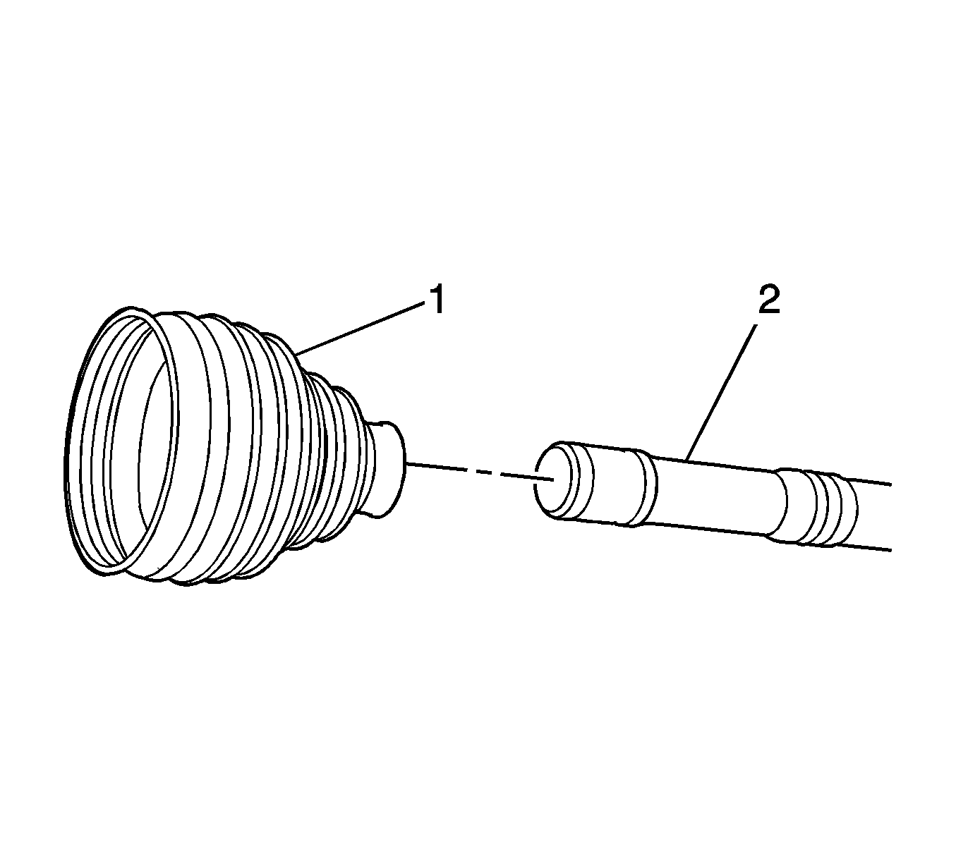
- Install the wheel drive shaft in a soft jawed vise.
- Using a hand grinder, remove and discard the swage clamp (4) from the boot (3).
- Using a pair of side cutters, remove and discard the outer boot clamp (2) from the boot (3).
- Using a hammer, a block of wood or a brass punch, remove the outer joint from the wheel drive shaft.
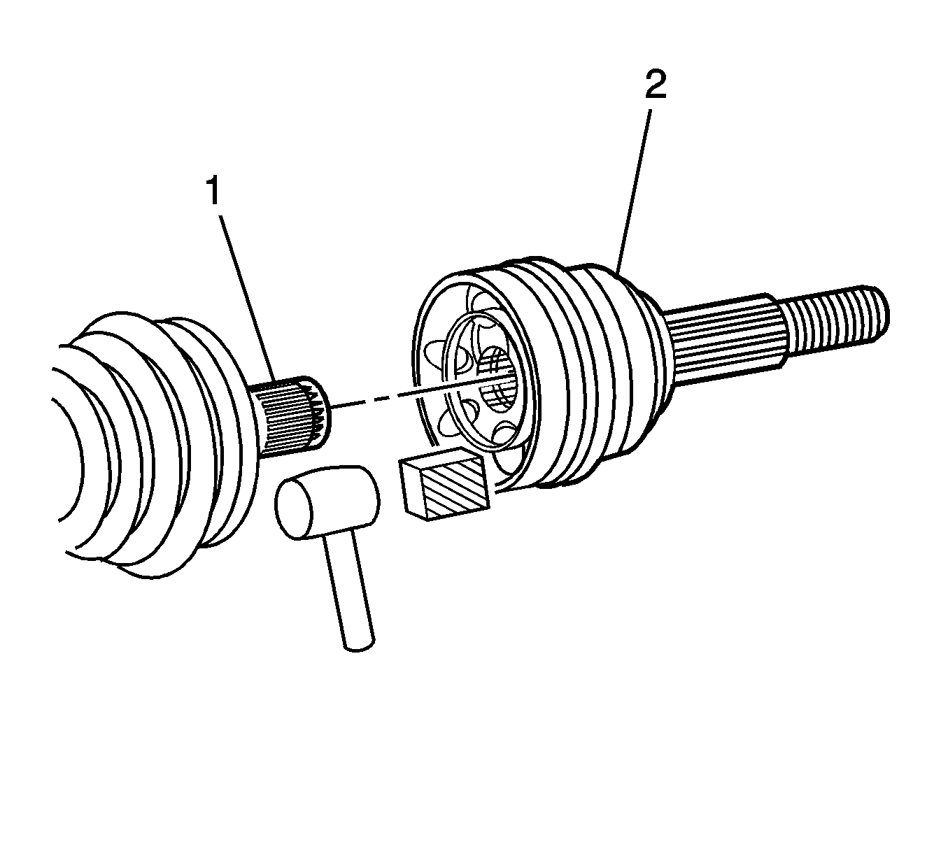
- Using the J 8059 , remove the inner (constant velocity) CV joint retaining ring (2) from the wheel drive shaft (1).
- Remove the CV joint boot (1) from the wheel drive shaft (2).
- Remove all the grease from the CV joint and the wheel drive shaft.
- Inspect the CV joint for excessive wear or defective components. Refer to Wheel Drive Shaft Outer Joint Inspection .

Notice: Do not cut through the wheel drive shaft inboard or outboard boot during service. Cutting through the boot may damage the sealing surface of the housing and the tripot or the constant velocity joint bushing. Damage to the sealing surface may lead to water and dirt intrusion and premature wear of the constant velocity joint.
Assembly Procedure
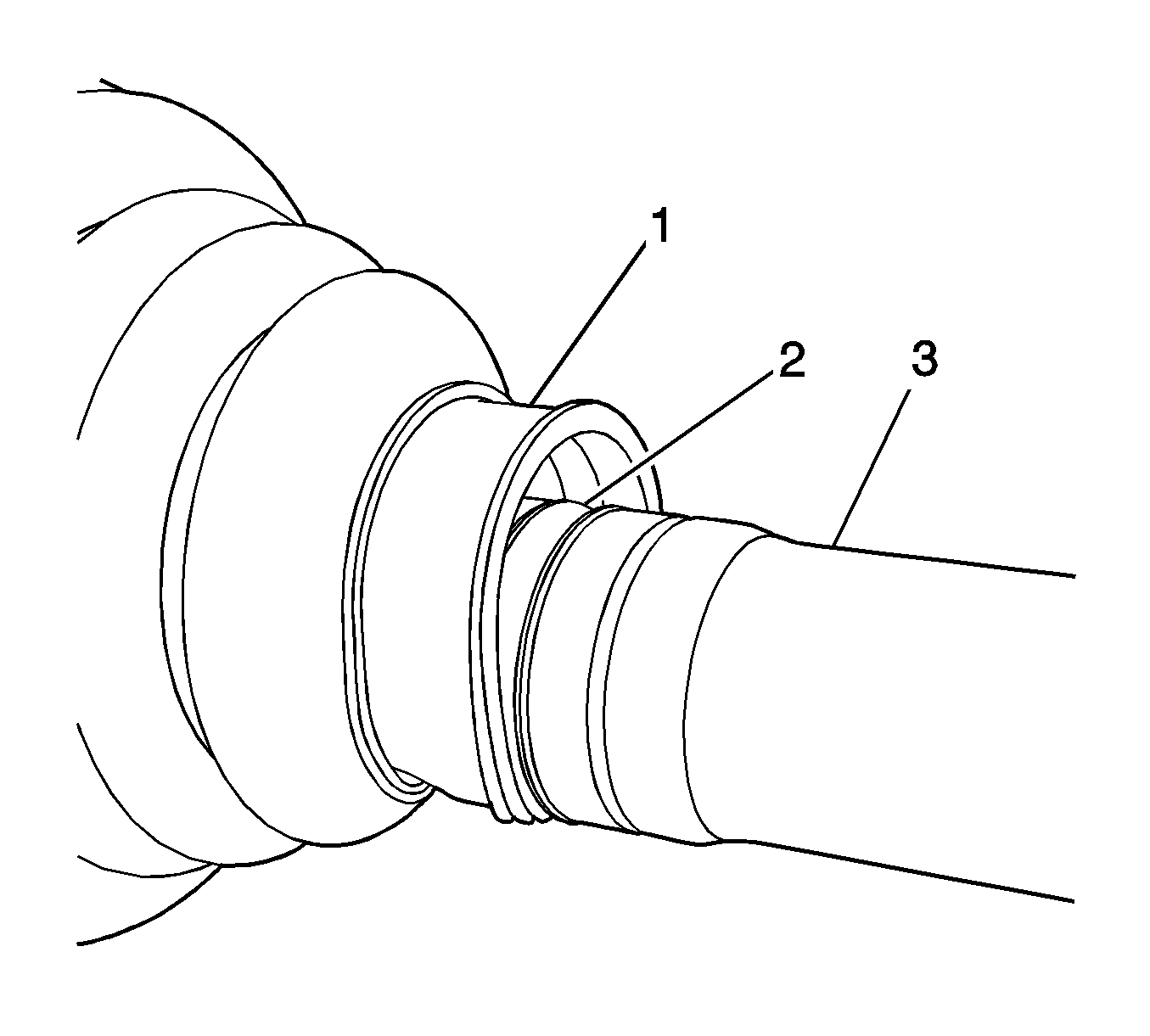
- Install the new swage clamp and boot (1) and the wheel drive shaft (1).
- Ensure that the boot (1) is properly seated in the groove (2) on the wheel drive shaft (3).
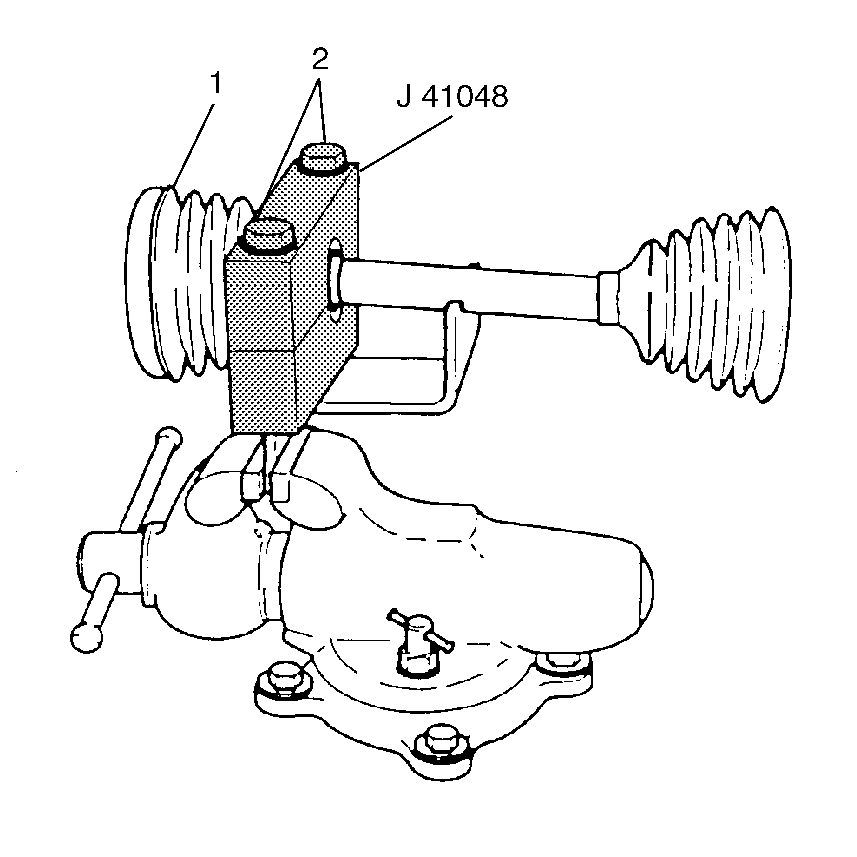
- Install the J 41048 in a vise.
- Position the wheel drive shaft and the boot (1) so that the swage clamp (2) is aligned in the J 41048 .
- Install the upper die on the wheel drive shaft.
- By hand, tighten the bolts (2) until the gap between the upper and lower die is equal.
- Tighten the bolts (2) equally one at a time until each one of the bolts have bottomed out.
- Remove the wheel drive shaft from the J 41048 .
- Reinstall the wheel drive shaft in the soft jawed vise.
- Install the inner retaining ring (2) on the wheel drive shaft 91).
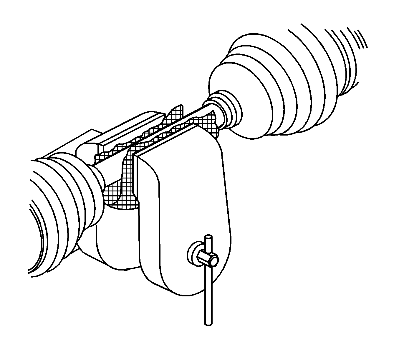
- Using a block of wood and a hammer, Install the outer CV joint on the wheel drive shaft.
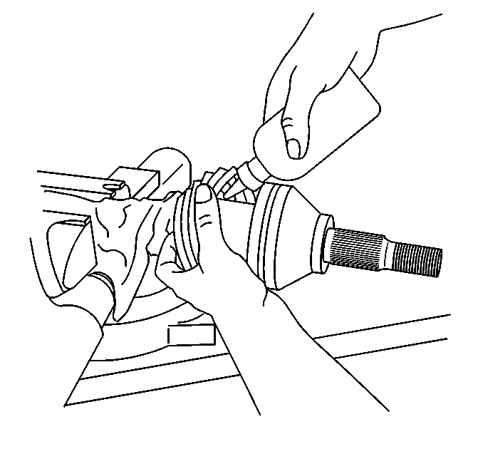
- Place approximately half of the grease from the service kit in the CV joint and in the boot.
- Install the outer boot and clamp (1) on the outer housing.
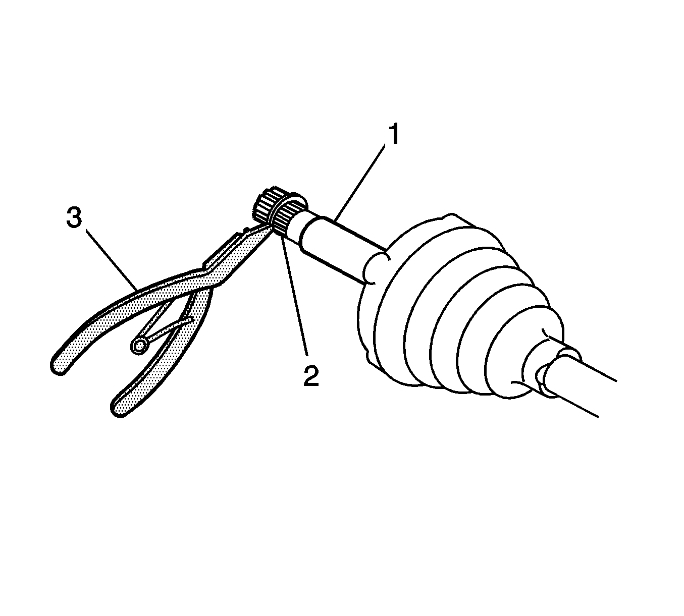
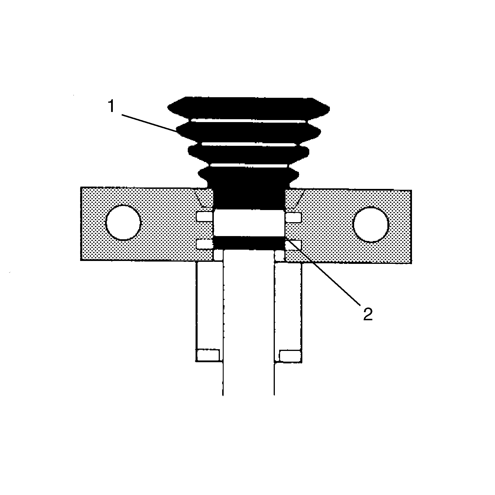
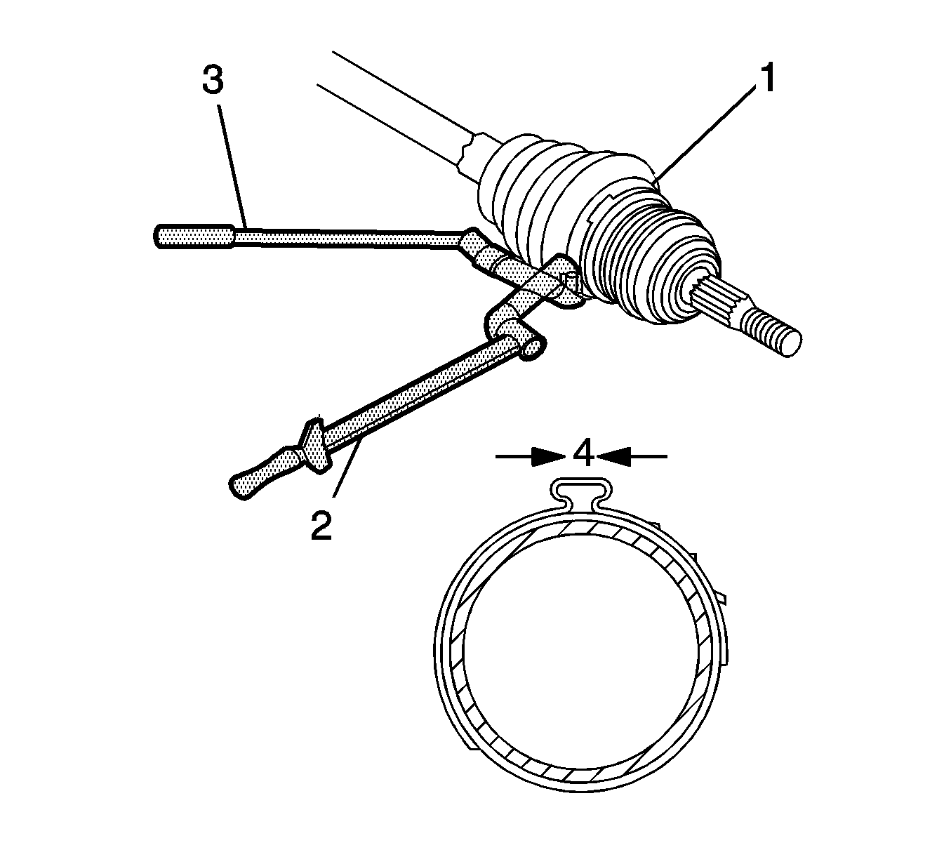
- Using the J 35910 with a breaker bar (3) and a torque wrench (2), tighten the clamp.
- Measure the gap (A) in the clamp. The gap should be 1.9 mm (5/64 inch).
- Rotate the outer joint several times to equally distribute the grease in the CV joint and the boot.
Important: Ensure that the clamp is in the correct position in the die, failure to do so will damage the clamp and the boot.

Important: The CV joint should just touch the inner retaining ring.
Important: Ensure that the clamp is properly aligned
Tighten
Tighten the clamp to 174 N·m (130 lb ft).
Important: If the gap does not read 1.9 mm (5/64 inch), continue to tighten the clamp until the specification is met.
