For 1990-2009 cars only
Removal Procedure
- Remove the tires and wheels. Refer to Tire and Wheel Removal and Installation .
- Remove the oil level indicator.
- Remove the engine splash shields. Refer to Engine Splash Shield Replacement .
- Drain the engine of oil.
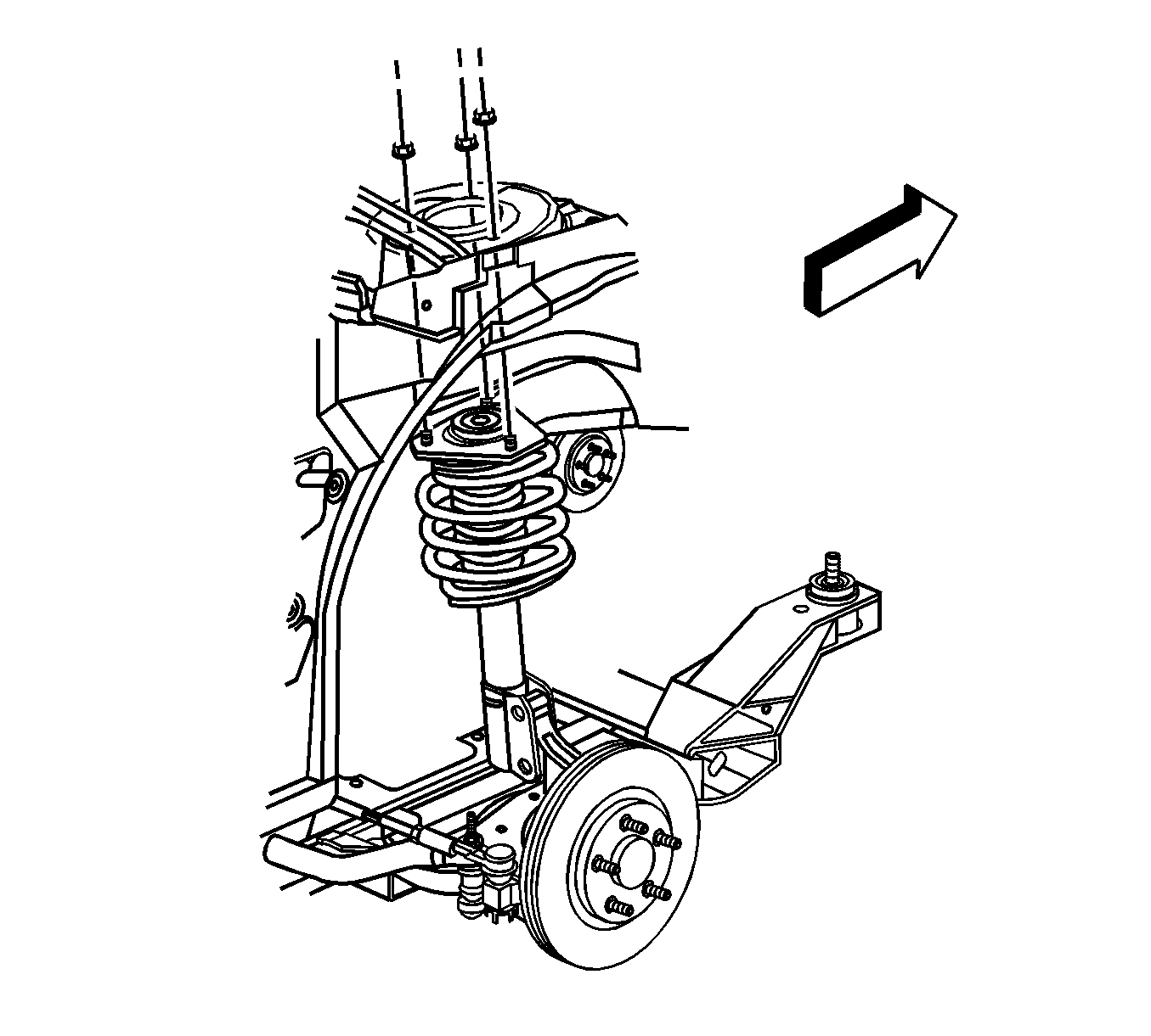
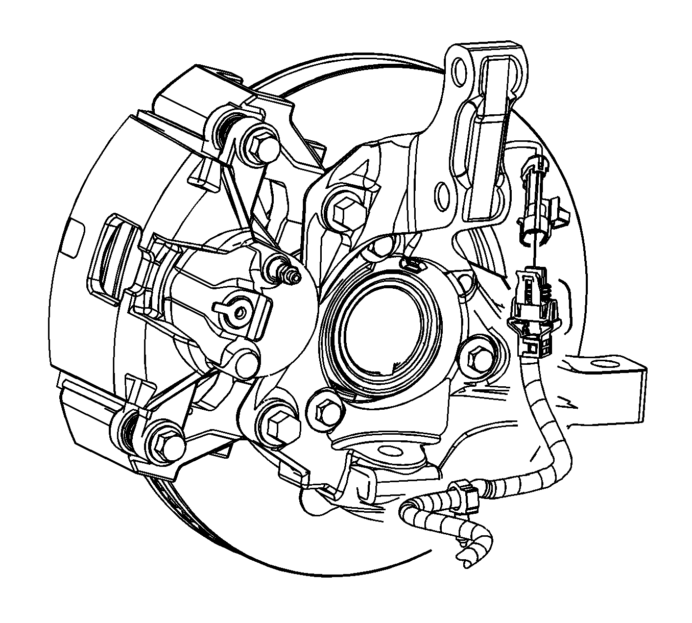
- Remove the brake calipers and relocate to the side. Refer to Front Brake Caliper Replacement .
- Remove the retaining bolts for the struts.
- Remove the steering rack from the frame. Refer to Steering Gear Replacement .
- Remove the tie rods from the steering knuckle. Refer to Rack and Pinion Outer Tie Rod End Replacement .
- Remove the power steering cooler lines from the retainers on the frame.
- Remove the transmission cooler lines from the retainers on the frame.
- Remove the battery cable wiring harness from the retainers on the frame.
- Disconnect the speed sensor electrical connectors.
- Remove the speed sensor wiring harness from the retainers on the frame.
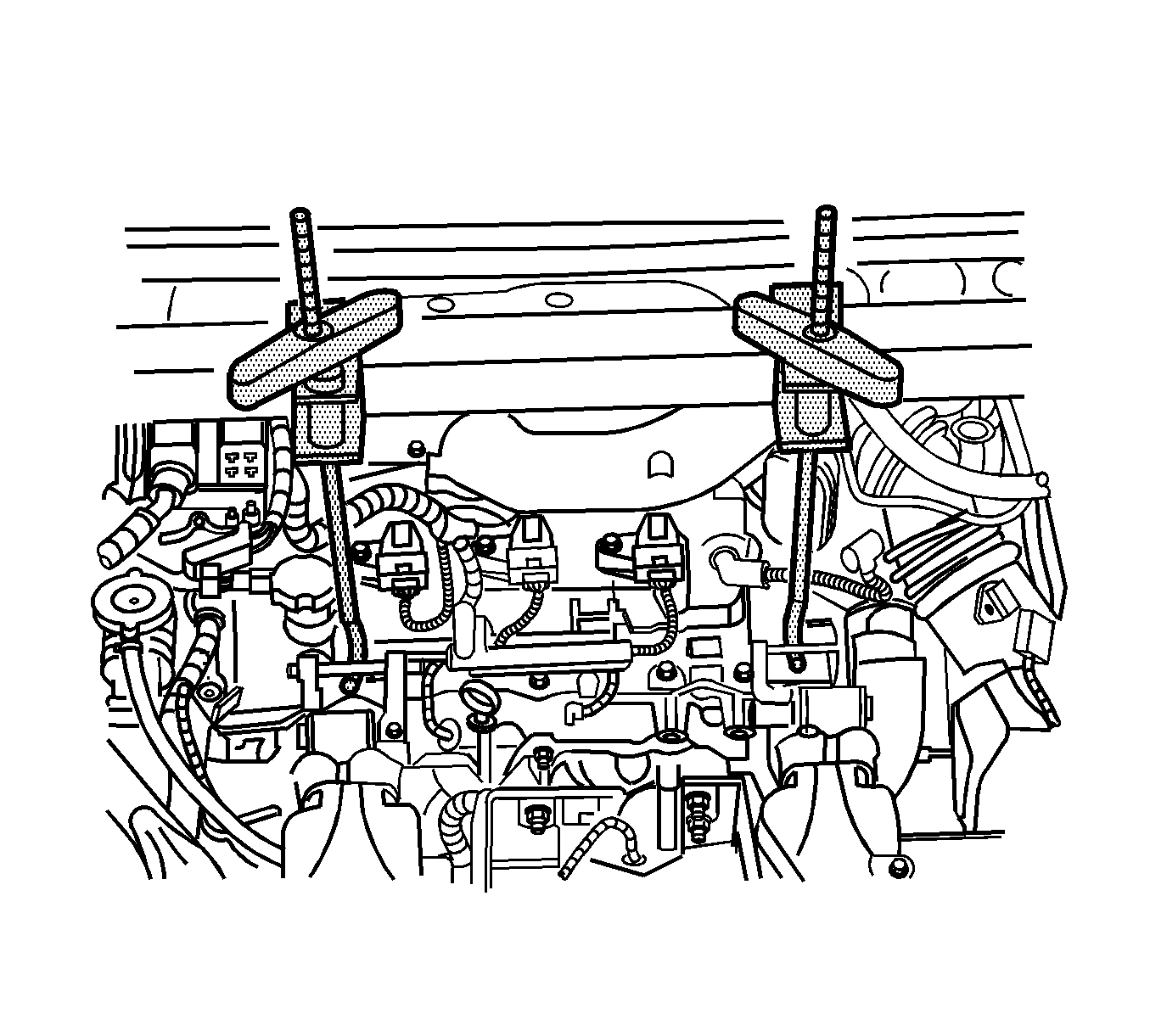
- Install the engine support fixture. Refer to Engine Support Fixture .
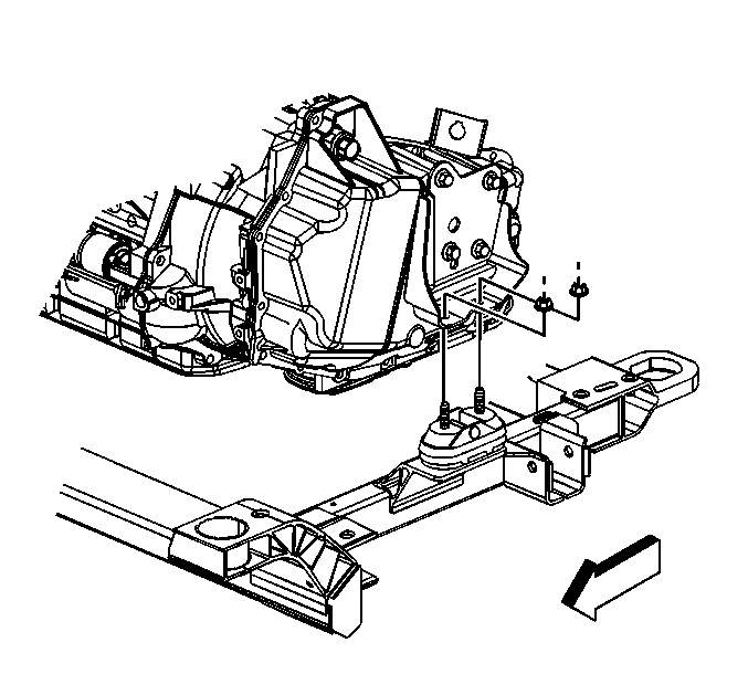
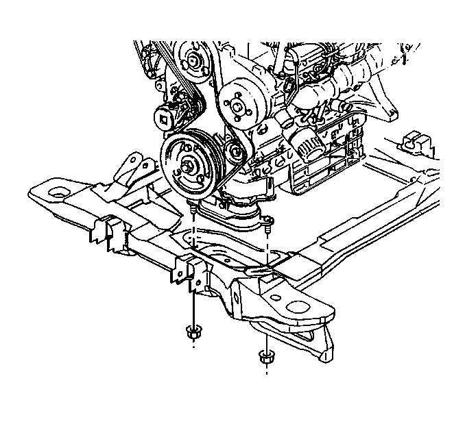
- Remove the right engine mount nuts.
- Remove the transmission mount bolts.
- Remove the engine mount struts. Refer to the following procedures:
- Remove the frame mounting bolts. Front shown, rear similar.
- Lower the frame. Refer to Frame Replacement .
- Disconnect the oil level senor electrical connector.
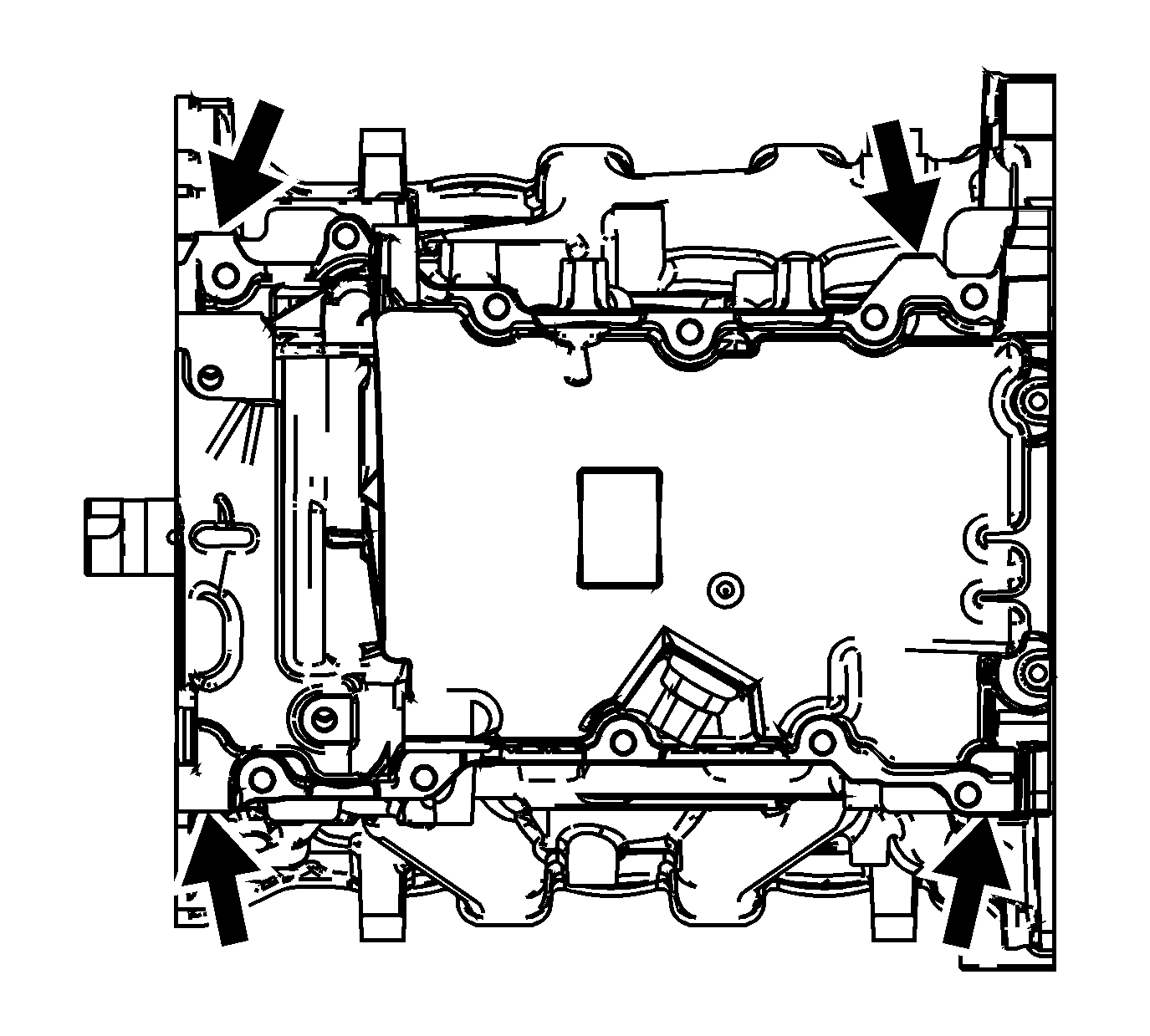
- Remove the oil pan bolts.
- Using the pry points on the oil pan, separate the oil pan from the engine block.
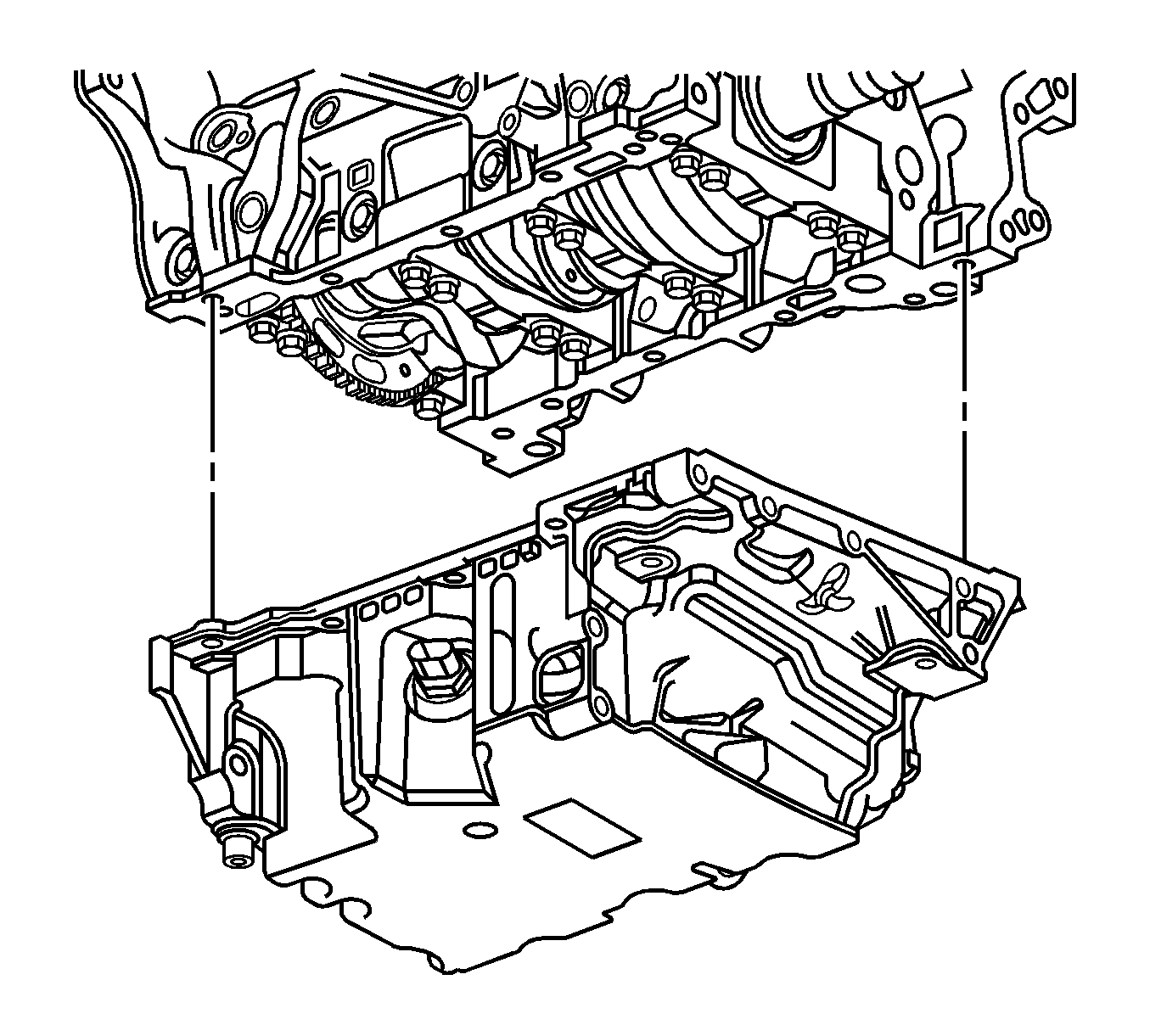
- Remove the oil pan from the vehicle.
- Disassemble the oil pan. Refer to Oil Pan Disassemble .
Important: In the following service procedure, DO NOT remove the brake calipers. Relocate them to the side and properly support them.
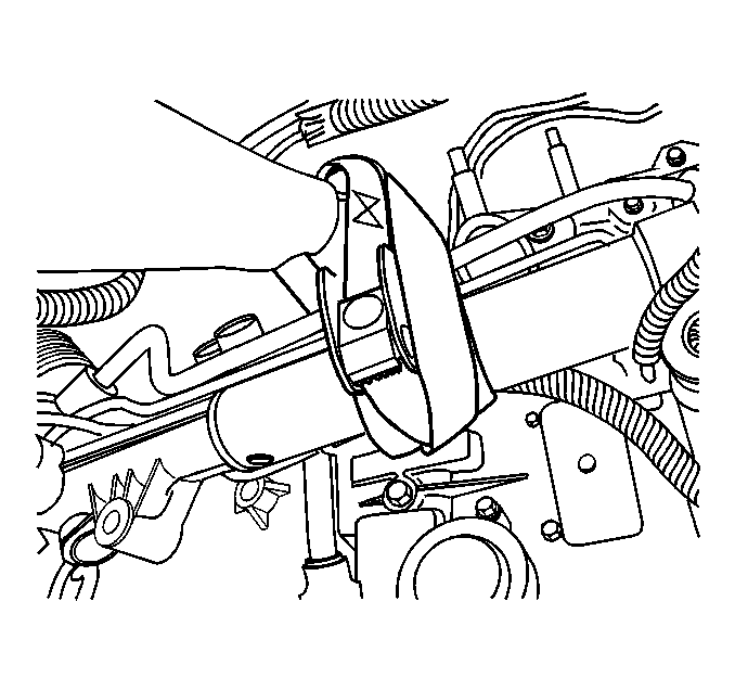
Important: In the following service procedure, DO NOT remove the steering rack from the vehicle. Relocate the steering rack and support the steering rack.
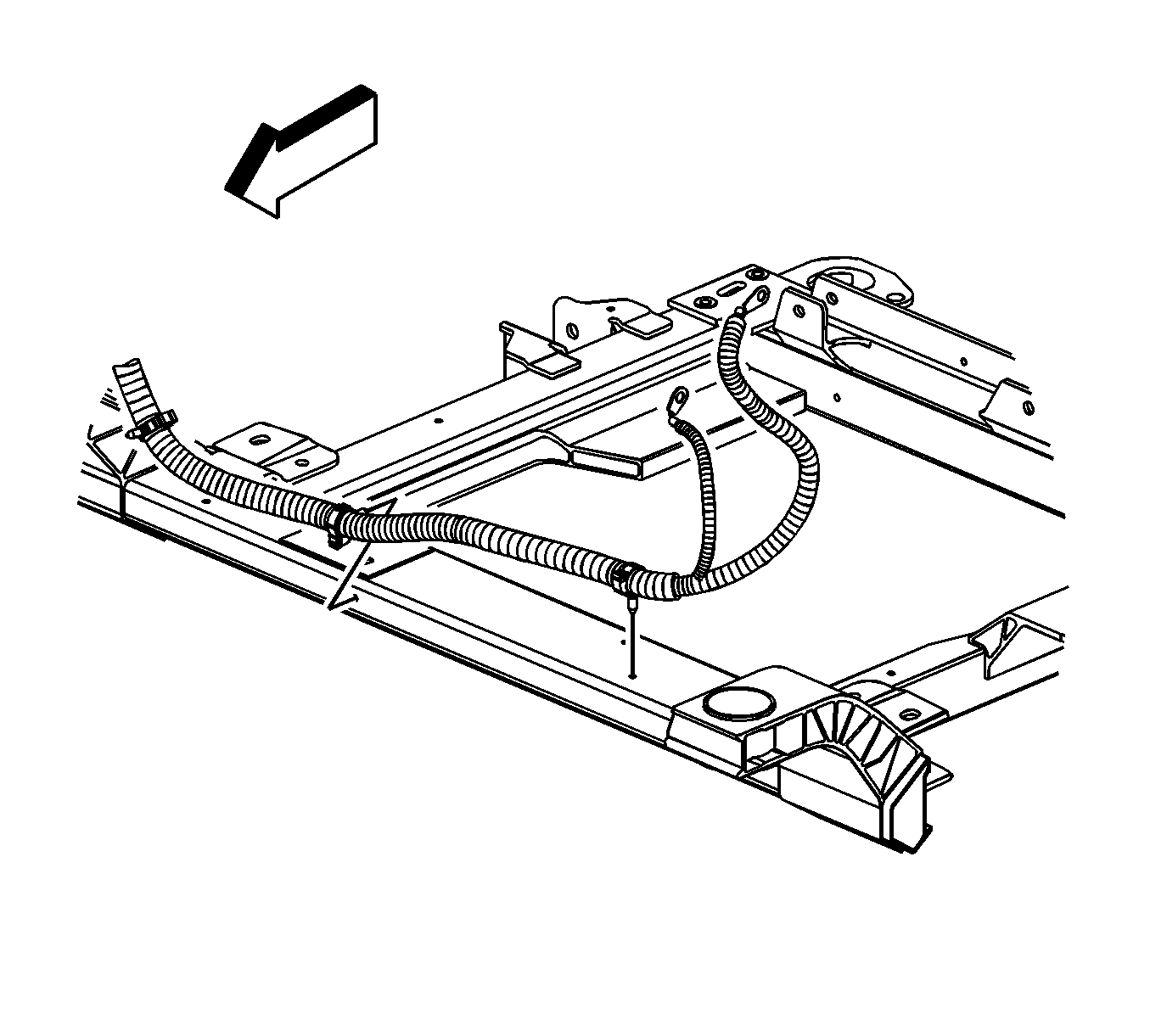
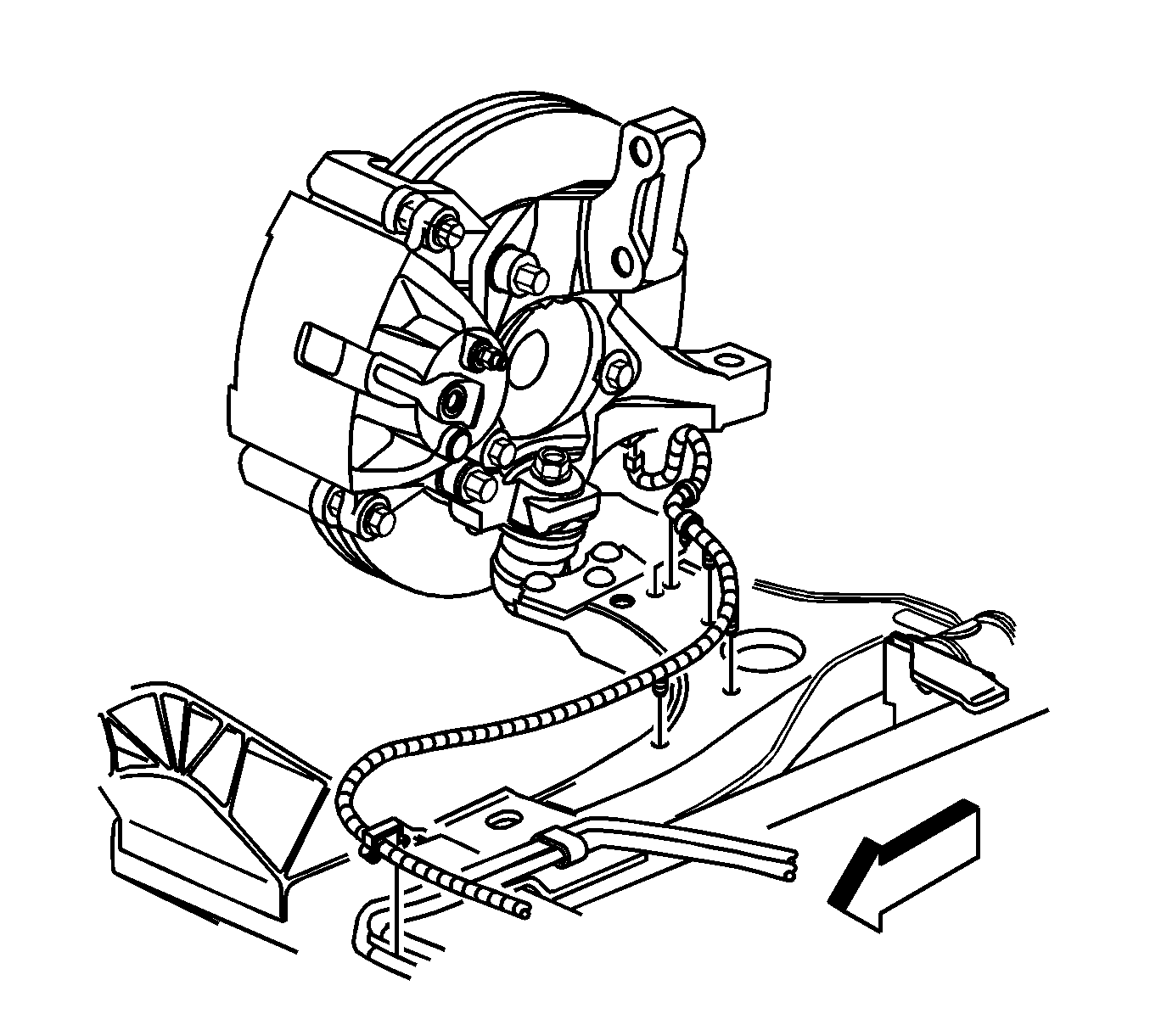
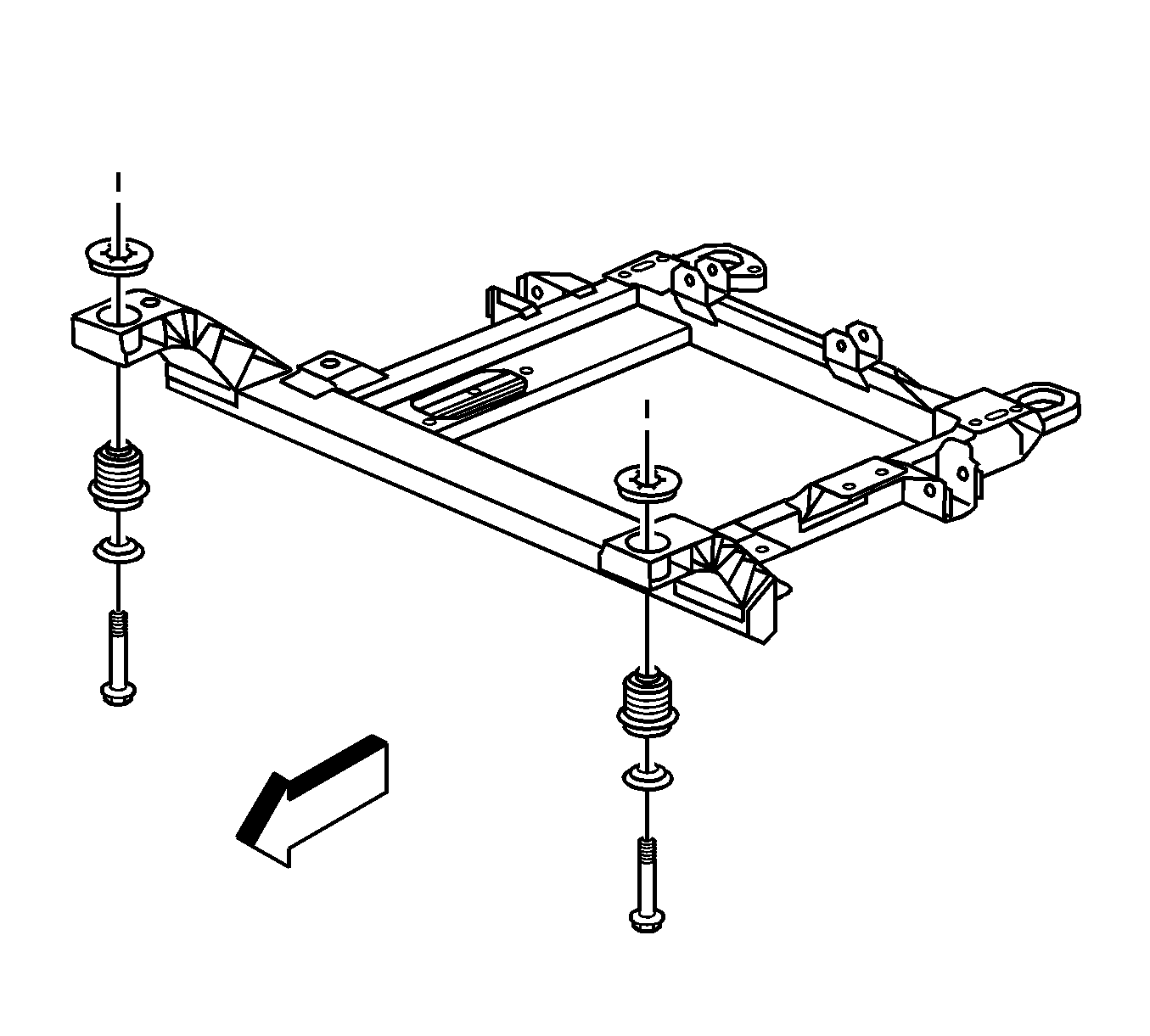
Important: Before lowering the frame, make sure that all transmission lines, power steering lines, and electrical harness have been disconnected and relocated to ensure that nothing will be damaged while lowering the frame.
Lower the frame enough to remove the oil pan assembly.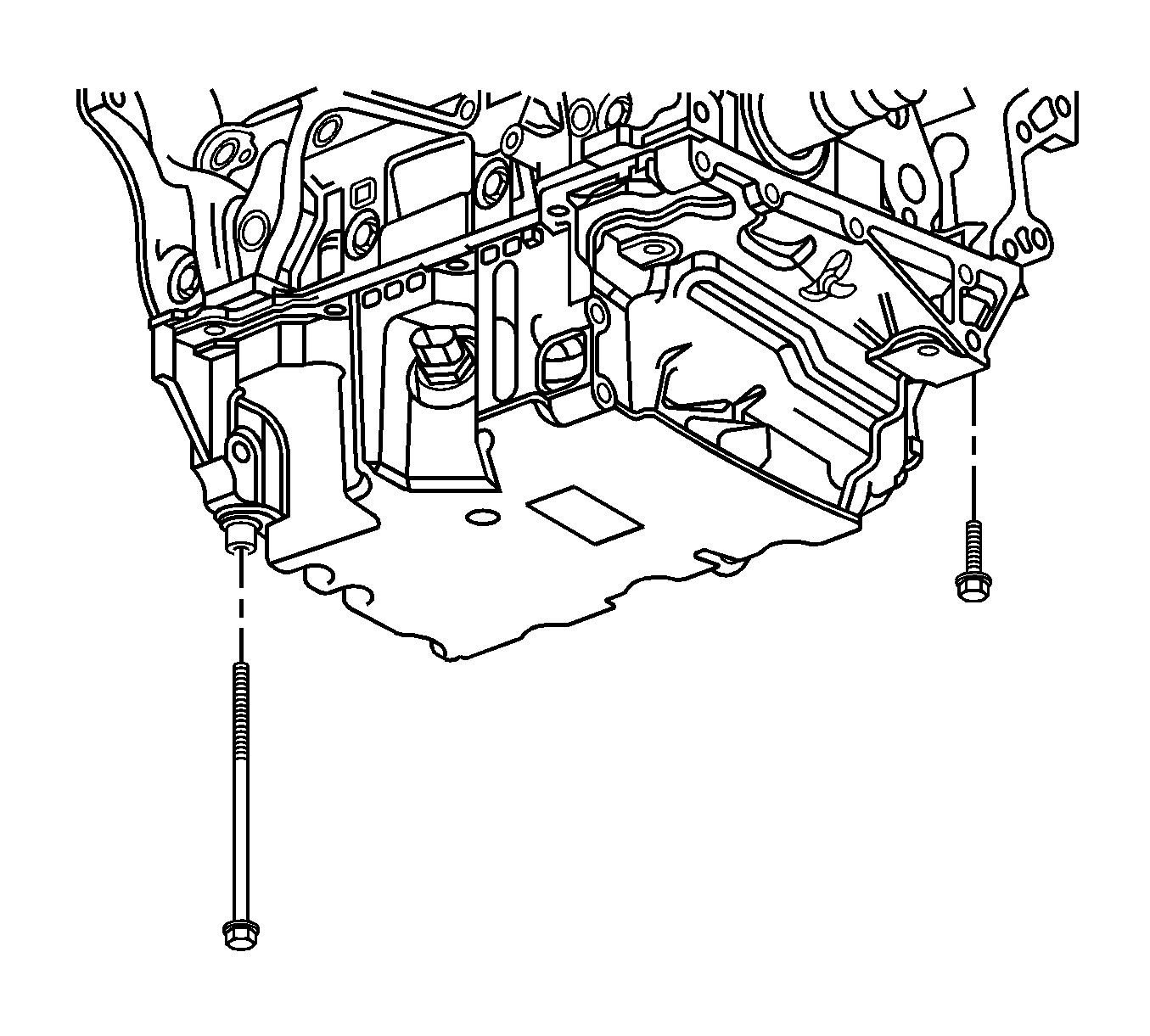
Installation Procedure
- Assemble the oil pan. Refer to Oil Pan Assemble .
- Install the oil pan. Refer to Oil Pan Installation .
- Connect the oil level senor electrical connector.
- Raise the frame. Refer to Frame Replacement .
- Install the transmission mount bolts. Refer to Transmission Mount Replacement - Left Side .
- Install the engine mount struts. Refer to the following procedures:
- Install the right engine mount nuts. Refer to Engine Mount Inspection .
- Remove the engine support fixture. Refer to Engine Support Fixture .
- Install the battery cable wiring harness in the retainers on the frame.
- Install the speed sensor wiring harness in the retainers on the frame.
- Connect the speed sensor electrical connectors.
- Install the transmission cooler lines in the retainers on the frame.
- Install the power steering lines in the retainers on the frame.
- Install the steering rack on the frame. Refer to Steering Gear Replacement .
- Install the tie rods in the steering knuckle. Refer to Rack and Pinion Outer Tie Rod End Replacement .
- Install the retaining bolts for the struts. Refer to Strut Assembly Replacement .
- Install the brakes calipers. Refer to Front Brake Caliper Replacement .
- Install the engine splash shields. Refer to Engine Splash Shield Replacement .
- Install the oil level indicate.
- Install the tires and wheels. Refer to Tire and Wheel Removal and Installation .
- Fill the engine with oil. Refer to Engine Oil and Oil Filter Replacement .

