For 1990-2009 cars only
Removal Procedure
- Disconnect the negative battery cable. Refer to Battery Negative Cable Disconnection and Connection .
- Remove the fuel injector sight shield. Refer to Fuel Injector Sight Shield Replacement .
- Remove the drive belt tensioner. Refer to Drive Belt Tensioner Replacement .
- Remove the right spark plug wires from the right spark plugs. Refer to Spark Plug Replacement .
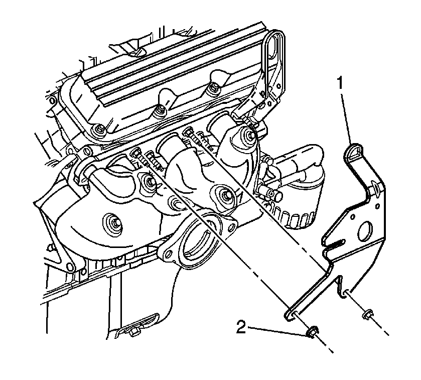
- Remove the fuel injector sight shield bracket nuts (2).
- Remove the fuel injector sight shield bracket (1).
- Remove the right engine lift bracket bolt (2) and the nut (3) from the engine lift bracket.
- Remove the right engine lift bracket (1) from the exhaust manifold.
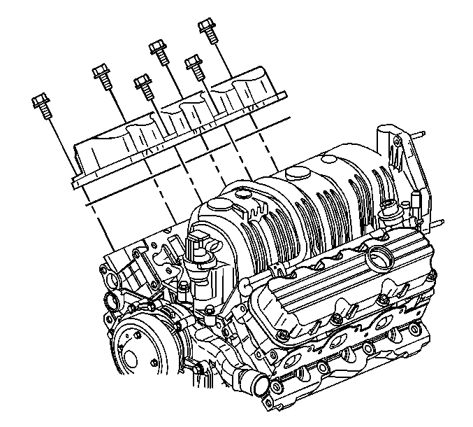
- Remove the right valve rocker arm cover bolts.
- Remove the right valve rocker arm cover.
- Remove the right valve rocker arm cover gasket.
- Clean the valve rocker arm cover gasket mating surfaces.
- Clean the valve rocker arm cover bolts of all thread locking adhesive.
Important: If the valve rocker arm cover adheres to the cylinder head, remove the valve rocker arm cover by bumping the end of the valve rocker arm cover with the palm of your hand or a soft rubber mallet.
Installation Procedure
- Install the new valve rocker arm cover gasket.
- Install the right valve rocker arm cover.
- Apply threadlock compound to the valve rocker arm cover bolt threads. Refer to Adhesives, Fluids, Lubricants, and Sealers for the correct part number.
- Install the right valve rocker arm cover bolts.
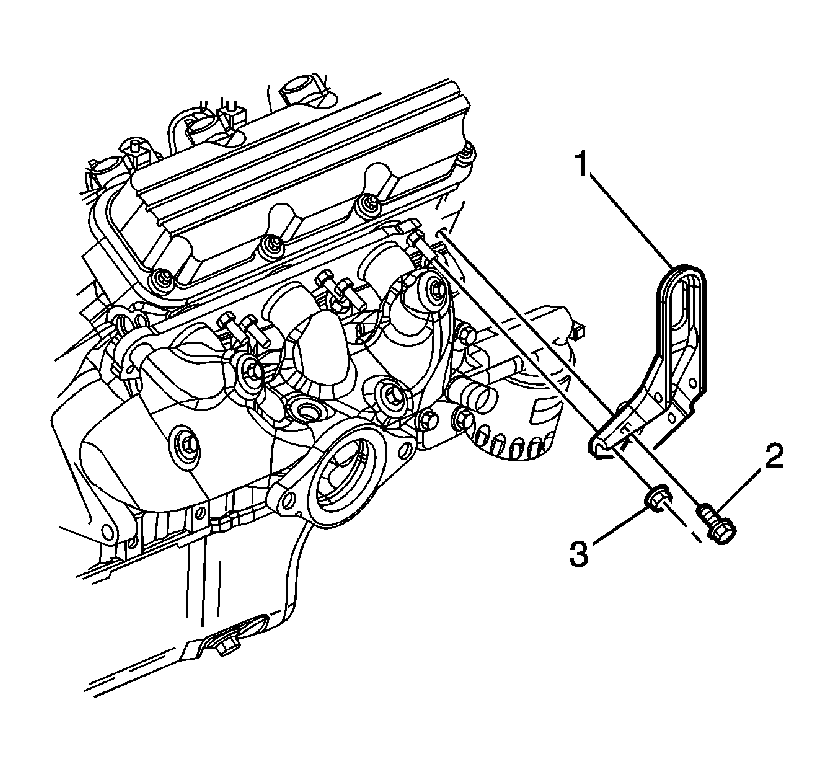
- Install the right engine lift bracket (1) to the exhaust manifold.
- Install the right engine lift bracket bolt (2) and the nut (3).
- Install the fuel injector sight shield bracket (1) to the exhaust manifold.
- Install the fuel injector sight shield bracket nuts (2).
- Install the right spark plug wires to the right spark plugs. Refer to Spark Plug Replacement .
- Install the drive belt tensioner. Refer to Drive Belt Tensioner Replacement .
- Install the fuel injector sight shield. Refer to Fuel Injector Sight Shield Replacement .
- Connect the negative battery cable. Refer to Battery Negative Cable Disconnection and Connection .
- Check and fill the crankcase as necessary.
- Inspect for oil leaks.
Important: Ensure that the valve rocker arm cover gasket is seated properly in the valve rocker arm cover groove.
Notice: Refer to Fastener Notice in the Preface section.
Tighten
Tighten the bolts to 10 N·m (89 lb in).
Tighten
Tighten the bolt and the nut to 30 N·m (22 lb ft).
Tighten
Tighten the nuts to 30 N·m (22 lb ft).
