For 1990-2009 cars only
Removal Procedure
- Remove the left instrument panel (I/P) insulator. Refer to Instrument Panel Insulator Panel Replacement - Left Side.
- Remove the driver knee bolster. Refer to Driver Knee Bolster Replacement.
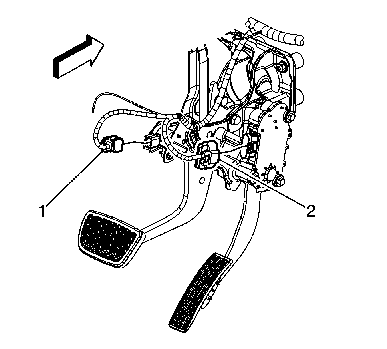
- Remove the I/P wiring harness electrical connector (2) from the accelerator pedal position (APP) sensor assembly.
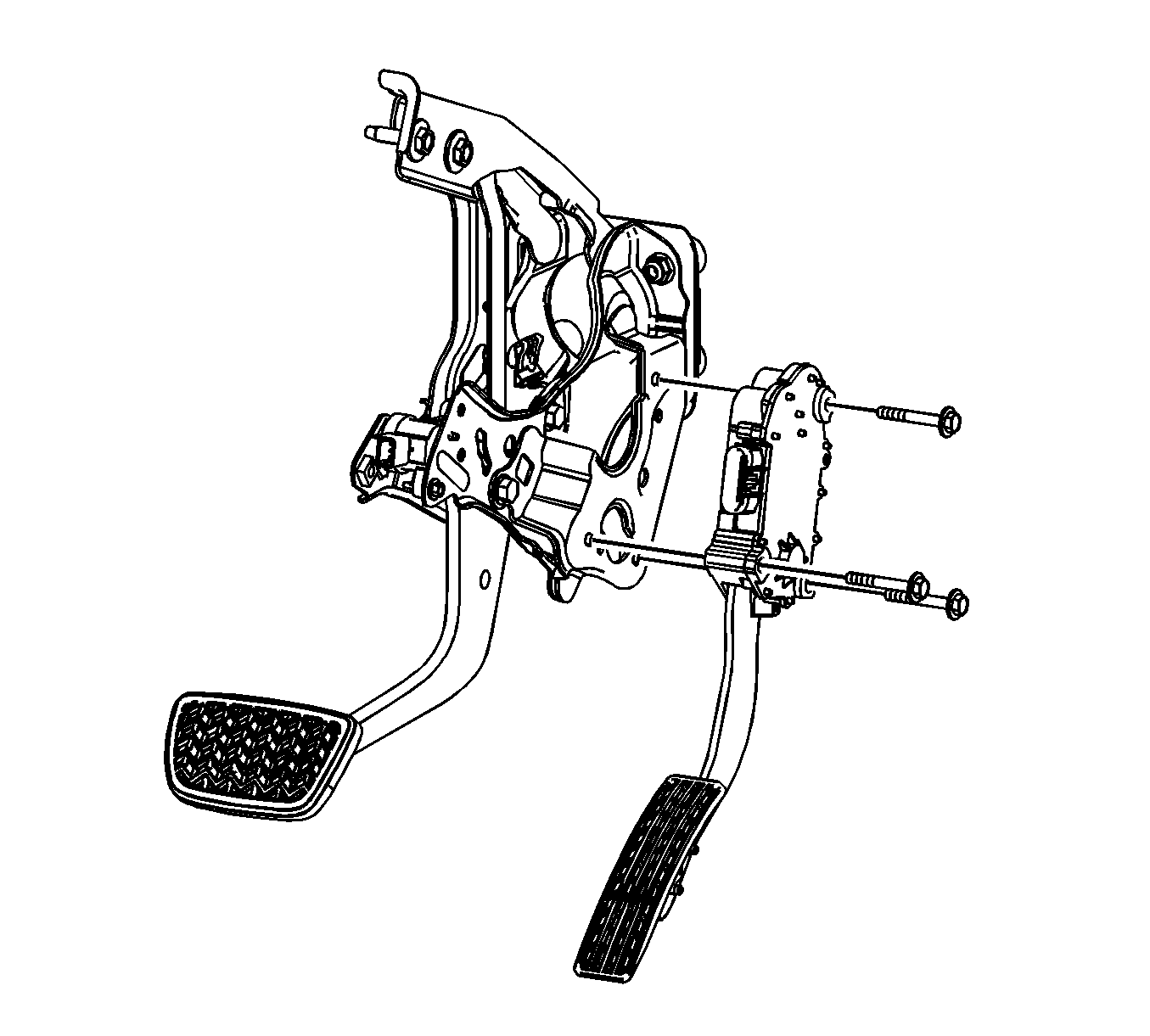
- Remove the APP sensor bolts and sensor assembly from the vehicle.


Note: Due to clearance issues, the upper attachment bolt cannot be removed from the APP sensor assembly. Loosen the bolt completely and leave the bolt in the component until the assembly is removed from the vehicle.
Installation Procedure
- Install the upper bolt into the APP sensor assembly.
- Install the APP sensor assembly into the vehicle.
- Install the remaining 2 lower APP sensor assembly bolts.
- Install the I/P wiring harness electrical connector (2) to the APP sensor assembly.
- Install the driver knee bolster. Refer to Driver Knee Bolster Replacement.
- Install the left I/P insulator. Refer to Instrument Panel Insulator Panel Replacement - Left Side.

Caution: Refer to Fastener Caution in the Preface section.
Tighten
Tighten the bolts to 8 N·m (71 lb in).

