Removal Procedure
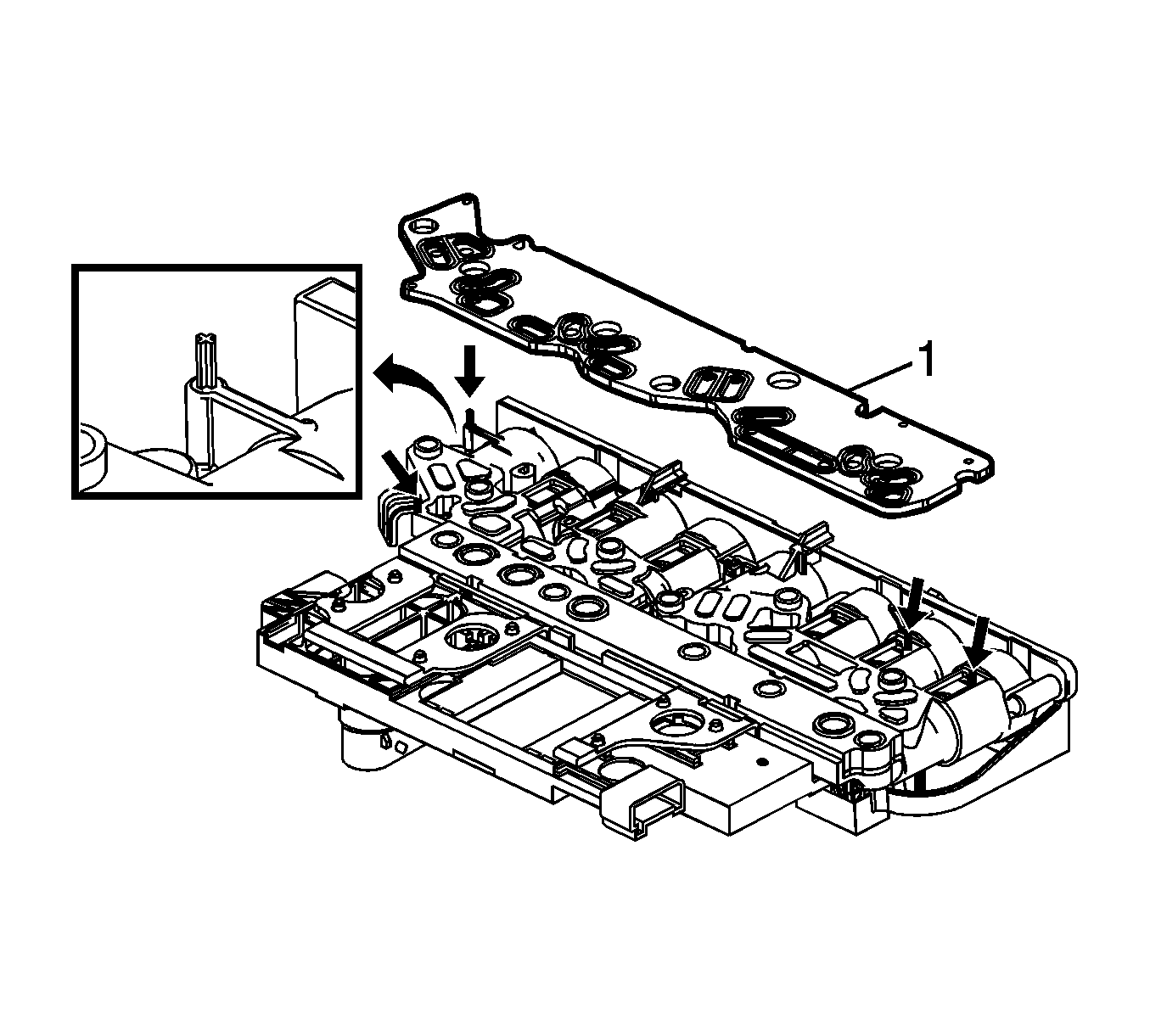
- Remove the control valve body cover. Refer to Control Valve Body Cover Replacement .
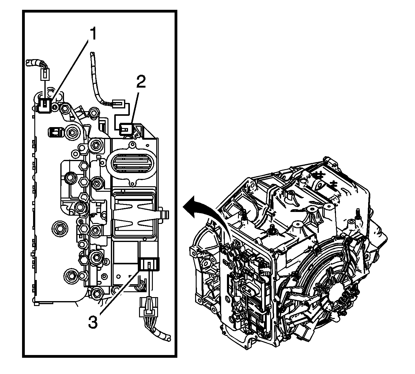
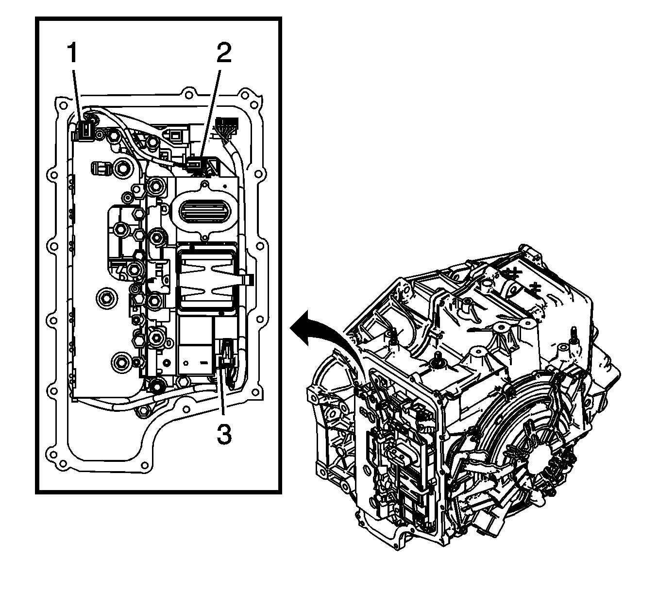
- Disconnect the input speed sensor electrical connector (1).
- Disconnect the output speed sensor electrical connector (2).
- Disconnect the shift position switch electrical connector (3).
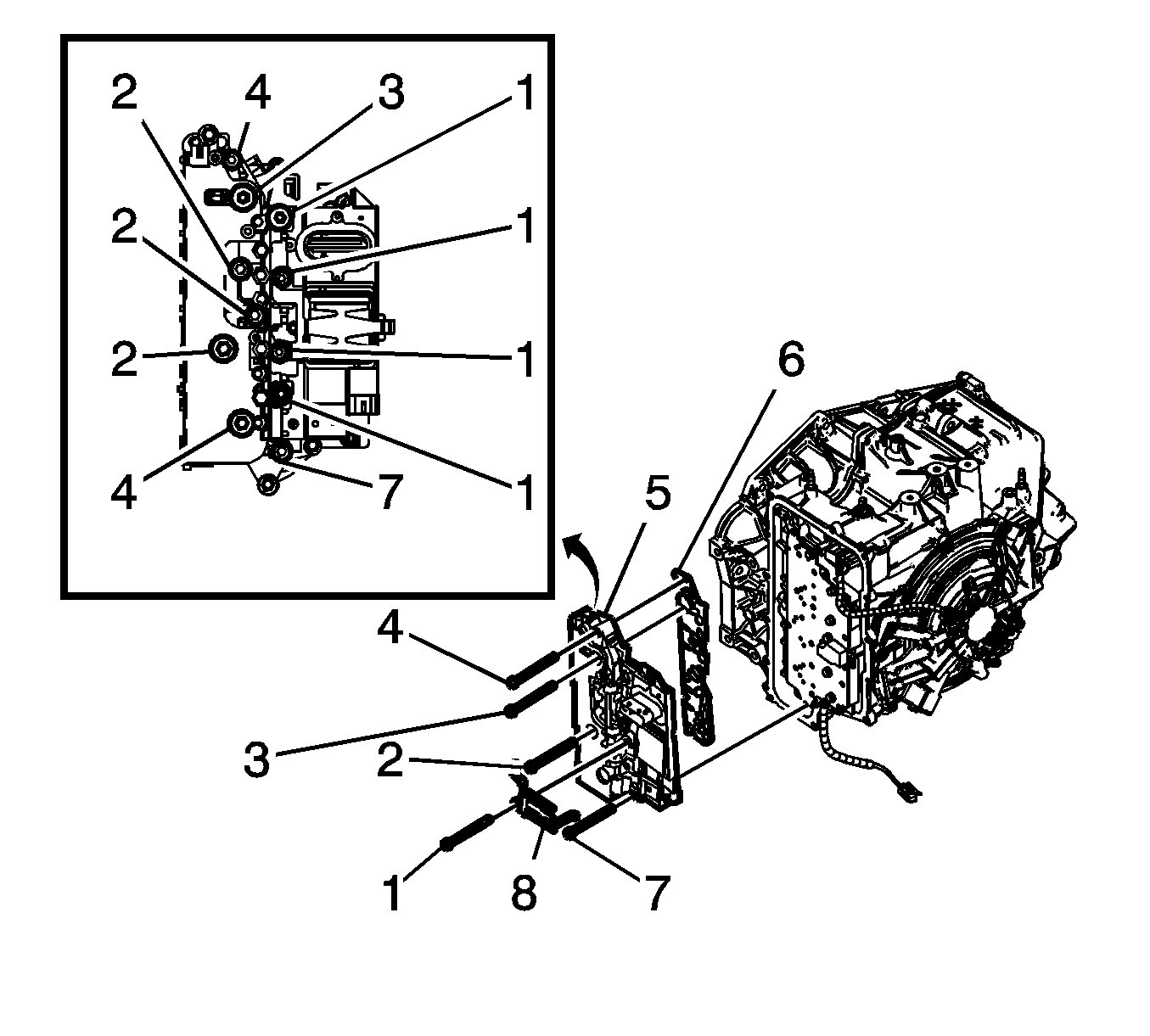
- Remove the 4 control valve body bolts (1) M6 x 80.
- Position the control solenoid valve spring (8) to the side. Spring will be released with the removal of the control valve body assembly.
- Remove the 2 control valve body bolts (4) M6 x 65.
- Remove the control valve body bolt (3) M6 x 42.
- Remove the 3 control valve body bolts (2) M6 x 95.
- Remove the control valve body bolt (7) M6 x 55.
- Remove the control solenoid valve body and transmission control module (TCM) assembly (5).
- Remove the control solenoid valve assembly filter plate (6).
Notice: Use care when removing or installing the filter plate assembly. A broken or missing retaining tab may not adequately secure the filter plate to the control solenoid valve assembly, resulting in possible damage or contamination.
| • | Discard the filler plate. It is not reusable. |
| • | Inspect the pressure switch manifold seals for damage or contamination. Replace the control solenoid valve assembly as necessary. |
| • | Inspect the upper channel plate bolt holes for damage, peening or burnelling. Any damage around the bolt holes near the pressure control switch (PCS) feed holes could cause leakage around the PCS seals. Replace the upper channel plate as necessary. |
Installation Procedure
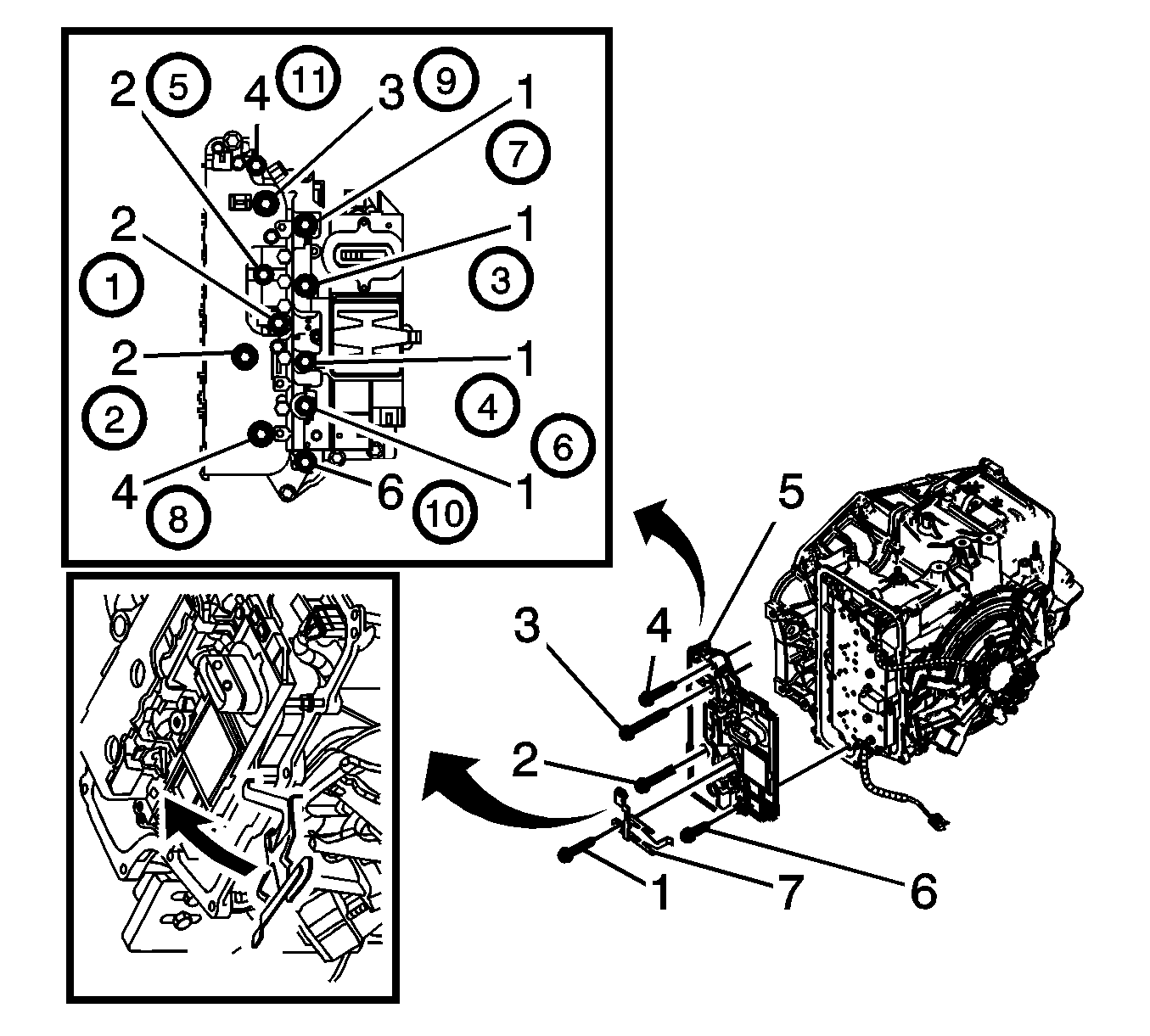
- Install a NEW control solenoid valve assembly filter plate (1).
- Install the control solenoid valve body and TCM assembly (5).
- Rotate the control solenoid valve spring (7) into position.
- Install the 4 control valve body bolts (1) M6 x 80.
- Install the control valve body bolt (6) M6 x 55.
- Install the 3 control valve body bolts (2) M6 x 95.
- Install the control valve body bolt (3) M6 x 42.
- Install the 2 control valve body bolts (4) M6 x 65.
- Connect the input speed sensor electrical connector (1).
- Connect the output speed sensor electrical connector (2).
- Connect the shift position switch electrical connector (3).
- Install the control valve body cover. Refer to Control Valve Body Cover Replacement .
- For transmission control module programming and setup. Refer to Control Module References .
- Perform the service fast learn adapt procedure. Refer to Service Fast Learn Adapts .
Notice: Use care when removing or installing the filter plate assembly. A broken or missing retaining tab may not adequately secure the filter plate to the control solenoid valve assembly, resulting in possible damage or contamination.
Notice: Refer to Fastener Notice in the Preface section.
Important: Install all bolts before tightening, then tighten in specified sequence.
Tighten
Tighten the bolts in sequence to 12 N·m (106 lb in).
Important: After an internal transmission repair or internal part replacement the service fast learn adapt procedure should be performed.
