SERVICE MANUAL UPDATE SEC. 6E3 DRIVEABILITY/EMISSION CODE 41

SUBJECT: SERVICE MANUAL UPDATE - SECTION 6E3 - DRIVEABILITY AND EMISSIONS REVISED CODE 41 CHART, FACING PAGE
VEHICLES AFFECTED: 1988-91 C/H 3800 (VIN C)
This bulletin updates the Code 41 Diagnostic Chart and Facing Page in "Driveability And Emissions" Section 6E3 for 3800 (VIN C) equipped 1988-1991 "H" Carlines and 1988-1990 "C" Carlines.
The revised chart addresses the possibility of a faulty ignition module causing Code 41 to be set by not supplying the CAM sensor signal to the ECM.
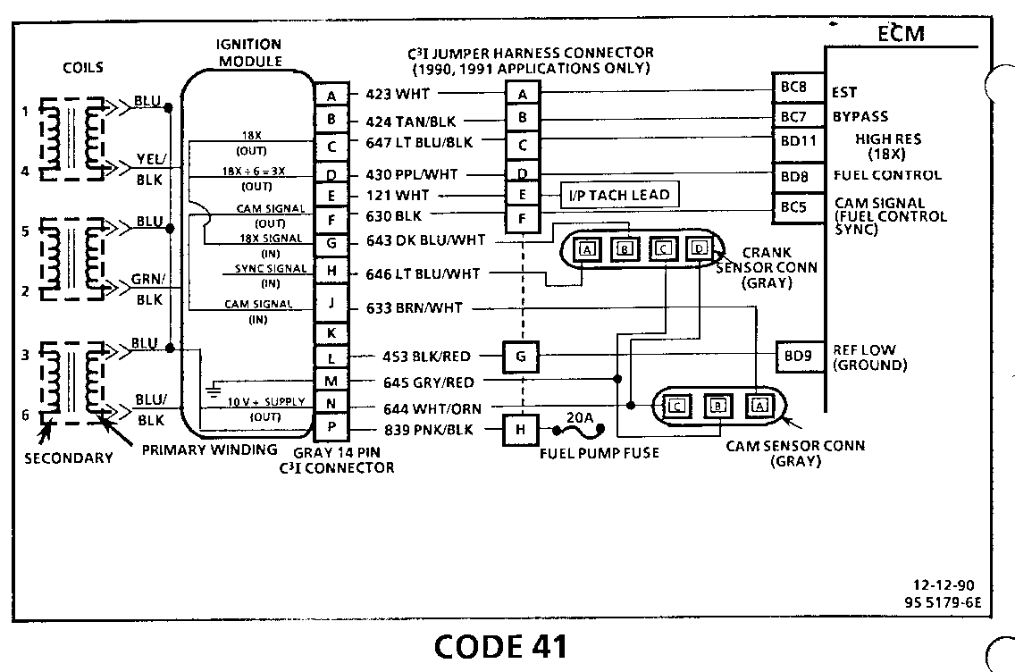
CODE 41
CAM SENSOR CIRCUIT 3800 (VIN C) (PORT)
Circuit Description:
The 3800 engine uses the simultaneous mode of fuel injection during start-up. As engine speed attains the 400 rpm level and a cam signal has been received by the ECM from the C31 module, the fuel injection switches modes to sequential injection. This is accomplished by use of a cam interrupter magnet and a cam sensor "hall effect" switch. The cam sensor sends a signal (sync-pulse) to the ignition module when cylinder #1 is 25" after top dead center on the compression stroke. This signal is used to start sequential fuel injection with the proper cylinder. If the cam signal is lost to the ECM, the engines fuel delivery will switch back to the simultaneous mode of operations. THE ENGINE WILL CONTINUE TO RUN. IT WILL RESTART AFTER SHUT DOWN.
Code 41 is set when the following conditions are met.
o Engine is running. o Cam sensor signal not received by ECM for last 2 seconds.
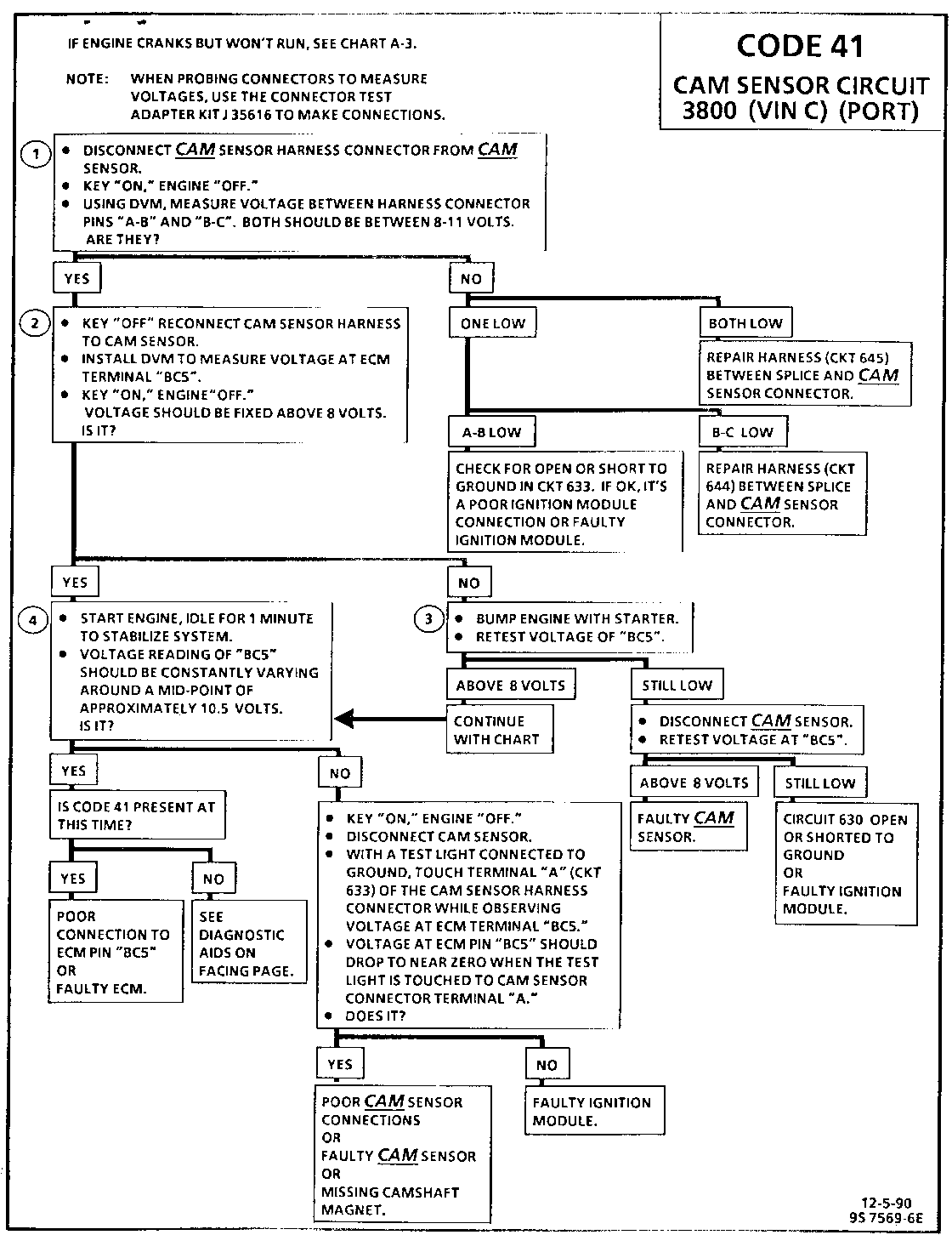
Test Description:
Numbers below refer to circled numbers on the diagnostic chart.
1. This step verifies proper operation of CKTs 633, 644, and 645.
2. Step verifies the integrity of CKT 630 from Ignition module to ECM.
3. If the camshaft gear magnet is interfacing with the cam sensor the voltage reading will be zero, bumping engine will cause the condition to away.
4. If the voltage reading of "BC5" is constantly varying and connection to the ECM is good, the ECM is faulty.
Diagnostic Aids:
An intermittent may be caused by a poor connection, rubbed through wire insulation or a wire broken inside the insulation. Check For:
o Poor Connection or Damaged Harness Inspect ECM harness connectors for backed out terminal "BC5", improper mating, broken locks, improperly formed or damaged terminals, poor terminal to wire connection and damaged harness.
o Intermittent Test If connections and harness check OK, monitor a digital voltmeter connected from ECM terminal "BC5" to ground while m related connectors and wiring harness. If the failure is induced, the voltage reading will change. This may help to isolate the location of the malfunction.
General Motors bulletins are intended for use by professional technicians, not a "do-it-yourselfer". They are written to inform those technicians of conditions that may occur on some vehicles, or to provide information that could assist in the proper service of a vehicle. Properly trained technicians have the equipment, tools, safety instructions and know-how to do a job properly and safely. If a condition is described, do not assume that the bulletin applies to your vehicle, or that your vehicle will have that condition. See a General Motors dealer servicing your brand of General Motors vehicle for information on whether your vehicle may benefit from the information.
