3 TERM.(UA8) BATTERY SYSTEM CONVERT TO COMMON BATTERY SYS.

VEHICLES AFFECTED: 1985 Electras Equipped With Option UA8 --------------------------------------
Buick Motor Division has discontinued the optional Power Reserve Battery System which was available on 1985 Electras. Due to the limited number of vehicles produced with this system, and to the possibility of customer inconvenience in obtaining service on this system, the following Special Policy has been established.
Vehicles produced with the Power Reserve System option UA8 will be converted to a more common battery system. This consists of replacing the three (3) terminal posi-power battery with a new two-terminal heavy duty UA1 option 78A72 battery and replacing the power reserve controller and battery cables with new battery cables.
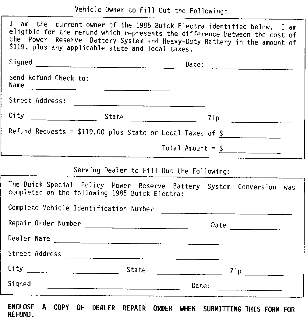
Owners of vehicles involved will be refunded the list price difference of $134.45 between the price of the two options, plus any applicable Provincial tax.
This Special Policy conversion will be done at no charge to the owner regardless of the vehicle age or mileage until August 31, 1986. After August 31, 1986, GM of Canada will continue the refund offer and the conversion of the power reserve system regardless of age or distance of vehicle at no charge, but the cost of the replacement or new battery will be at the customer's expense.
A copy of this 'Special Policy Bulletin,' should be filed in the 3-ring binder furnished to the Dealer by General Motors in September 1982.
VEHICLES INVOLVED
All 1985 Electras equipped with Delco Power Reserve Freedom Battery System Option UA8.
OWNER NOTIFICATION AND REFUND
Owners of vehicles involved in this Special Policy will be notified by GM of Canada (see copy of Owner Letter included with this bulletin). OWNER REFUND WILL BE PROVIDED, BY THE DEALER AND CLAIMED AS A NET AMOUNT (SEE CLAIM INFORMATION).
PARTS INFORMATION
The parts required to perform this conversion on one vehicle is as follows:
Quantity Description Part Number -------- ----------- ----------- 1 Battery 78A72 1 Battery Cable Assembly 12038872
TECHNICAL PROCEDURE
1. Raise vehicle hood and cover fenders.
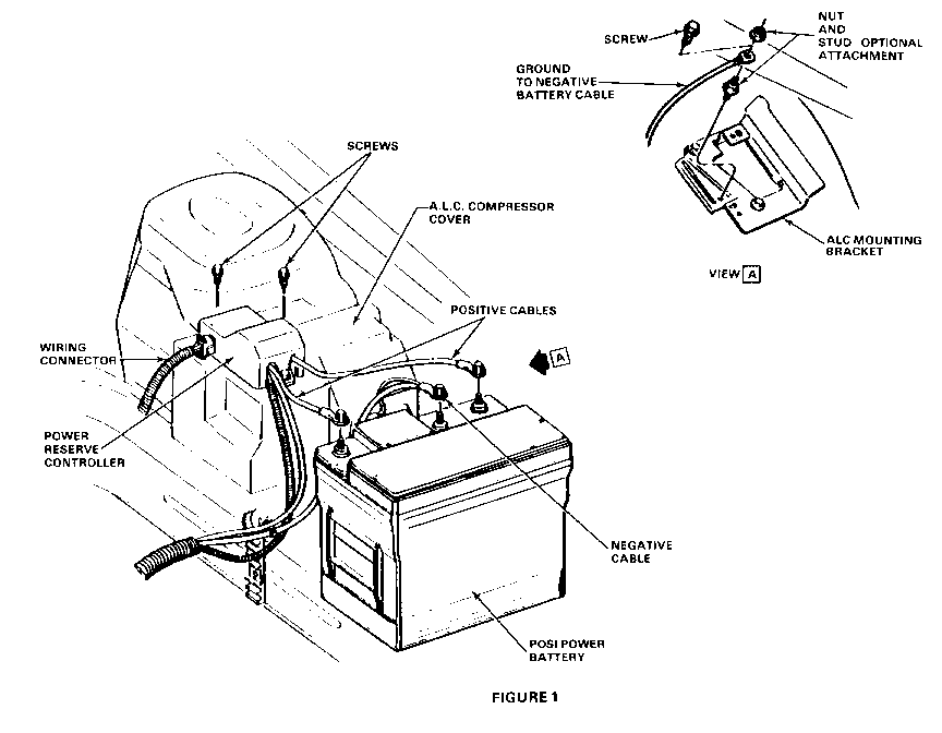
2. Disconnect negative cable (black, centre cable) from battery and both positive cables from battery. Refer to Figure 1.
3. Remove battery hold-down bolt, washer, and hold-down clamp.
4. Remove posi-power battery and hold for disposition by Zone Personnel.
CAUTION:
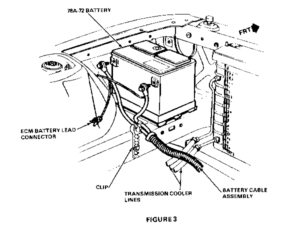
FOLLOW RECOMMENDED PRECAUTIONS IN HANDLING BATTERIES -------------------------------------------------------------- 5. Disconnect ECM battery lead connector. (Refer to Figure 3)
6. Detach wiring harness connector from controller. Insulate connector with electrical tape. Refer to Figure 1.
7. Remove controller mounting screws. Reinstall screws in ALC cover after removing controller.
8. Remove ALC compressor cover.
9. Disconnect sheet metal ground wire under ALC compressor cover. Refer to Figure 1, View A.
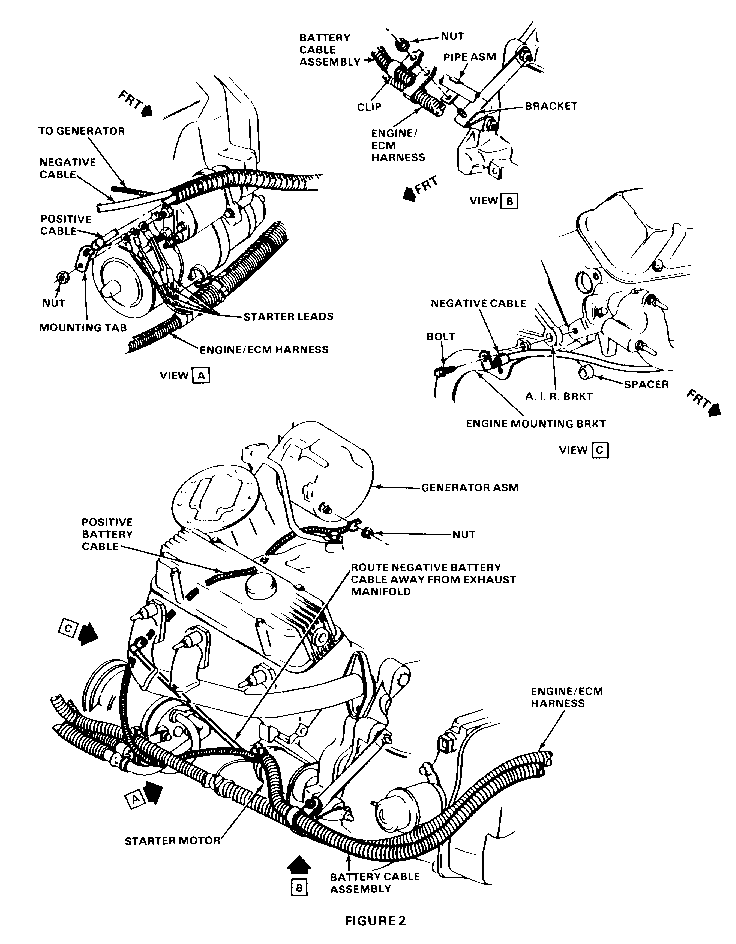
10. Disconnect battery cable harness from generator, starter, and engine ground. Refer to Figure 2, View A and C.
11. Disconnect battery cable clip at bracket at rear of engine. Refer to Figure 2, View B.
12. Remove battery cable assembly with controller attached and hold for disposition by Zone Personnel.
13. Replace battery cable assembly with part number 12038872. Follow same routings as removed cables to engine, starter, and generator using the Figures and torques as follows:
Attachment Reference Torque Specification ---------- --------- -------------------- Positive Cable to Figure 2 5.7 N.m (4-5 lb. ft.) Generator
Positive Cable to Figure 2, 14-20 N.m (10-15 lb. ft.) Starter View A
Negative Cable to Figure 2, 40-60 N.m (30-44 lb. ft.) Engine View C
Sheet Metal Figure 1, 6-9 N.m (4-7 lb. ft.) Ground View A
Cable Assembly Figure 2, 8-11 N.m (6-8 lb. ft.) Clip to Engine View B
NEGATIVE CABLE MUST BE ROUTED AWAY FROM EXHAUST MANIFOLD. (REFER TO FIGURE 2)
14. Connect ECM battery lead connector. (Refer to Figure 3)
15. Install controller wiring harness detached in step 6 under ALC compressor cover and secure to ALC harness with electrical tape.
16. Install ALC compressor cover.
17. Install new 78A72 battery. Do not connect battery cables at this time.
18. Reassemble hold-down clamp and secure battery in place. Torque bolt to 15-20 N.m (11-15 lb. ft.)
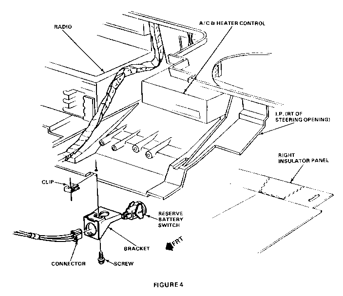
19. Remove right lower instrument insulator panel. Disconnect. battery reserve switch connector to switch under dash (Refer to figure 4).
20. Remove switch, switch bracket screw, and remove bracket and nut.
21. Tape switch connector and wiring to instrument panel wiring harness to prevent rattling. Reinstall lower instrument insulator panel.
22. Attach positive cable (red) to battery positive (+). Torque to 16-20 N.m (12-15 lb. ft.). (Refer to Figure 3)
23. Attach negative cable (black connector) to battery negative (-). Torque to 16-20 N.m (12-15 1-b. ft.)
24. Start vehicle and check electrical operation. Close hood.
NOTE: Disconnection of battery will cause loss of any electronic memory settings.
DISPOSITION OF REPLACED PARTS
Replaced parts must be held for disposition by Zone contact personnel. Each replaced part must have a claim tag attached showing the repair order and the VIN of the vehicle from which it was removed.
CLAIM INFORMATION
Credit will be issued upon receipt of a properly prepared special policy claim. Standard repair order information must be entered along with the following:
A. PERFORM POWER RESERVE SYSTEM CONVERSION PRIOR TO SEPTEMBER 1, 1986 ----------------------------------------------------------------------
Parts Failed Part Parts Labour Operation Labour Net Item Count Number Amount Number Hours Amount ----- ----------- ------ ---------------- ------ -------- 2 78A72 * T5102 .6 Hrs. **
* Enter the Dealer Net Price (in effect at the time of repair), Plus 30% for the Battery Part No. 78A72 and Cable Assembly Part No. 12038872.
** Enter $134.45 Plus Any Applicable Provincial Sales Tax. (I.E. - the difference between the price of the two options).
B. PERFORM POWER RESERVE SYSTEM CONVERSION AFTER AUGUST 31, 1986
Parts Failed Part Parts Labour Operation Labour Net Item Count Number Amount Number Hours Amount ----- ----------- ------ ---------------- ------ -------- 1 12038872 *** T5103 .6 Hrs. ****
*** Enter the Dealer Net Price (in effect at the time of repair), Plus 30% for the Cable Assembly Part No. 12038872.
**** Enter $134.45 Plus Any Applicable Provincial Sales Tax. (i.e. - the difference between the price of the two options).
Zone authorization is required on all claim submissions associated with this Special Policy.
General Motors bulletins are intended for use by professional technicians, not a "do-it-yourselfer". They are written to inform those technicians of conditions that may occur on some vehicles, or to provide information that could assist in the proper service of a vehicle. Properly trained technicians have the equipment, tools, safety instructions and know-how to do a job properly and safely. If a condition is described, do not assume that the bulletin applies to your vehicle, or that your vehicle will have that condition. See a General Motors dealer servicing your brand of General Motors vehicle for information on whether your vehicle may benefit from the information.
