SERVICE MANUAL UPDATE SEC. 8A CRUISE MODULE BRAKE SWITCH

SUBJECT: SERVICE MANUAL UPDATE - SECTION 8A - CRUISE MODULE MECHANIZATION, NORMAL BRAKE SWITCH STATE
VEHICLES AFFECTED: 1992 "B"
This bulletin is being revised for Buick only. A Statement has been added to the first paragraph regarding the 1992 Roadmaster Sedan, and a paragraph has been added at the end of the bulletin for Buick only.
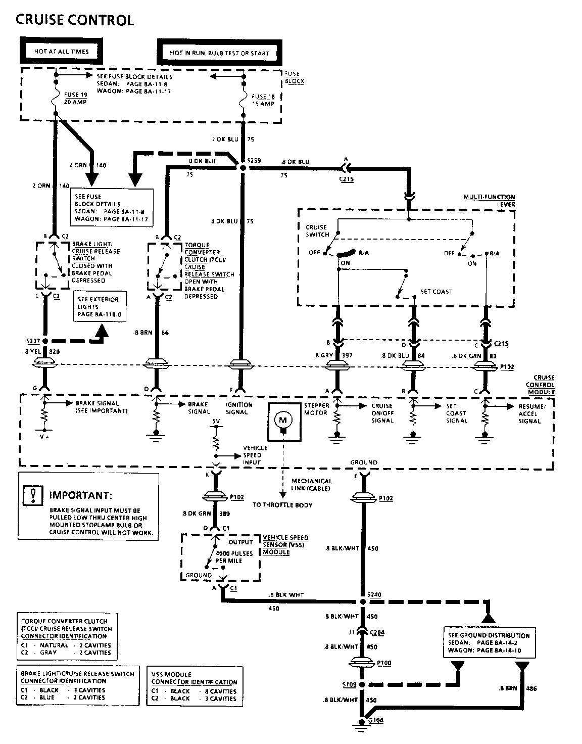
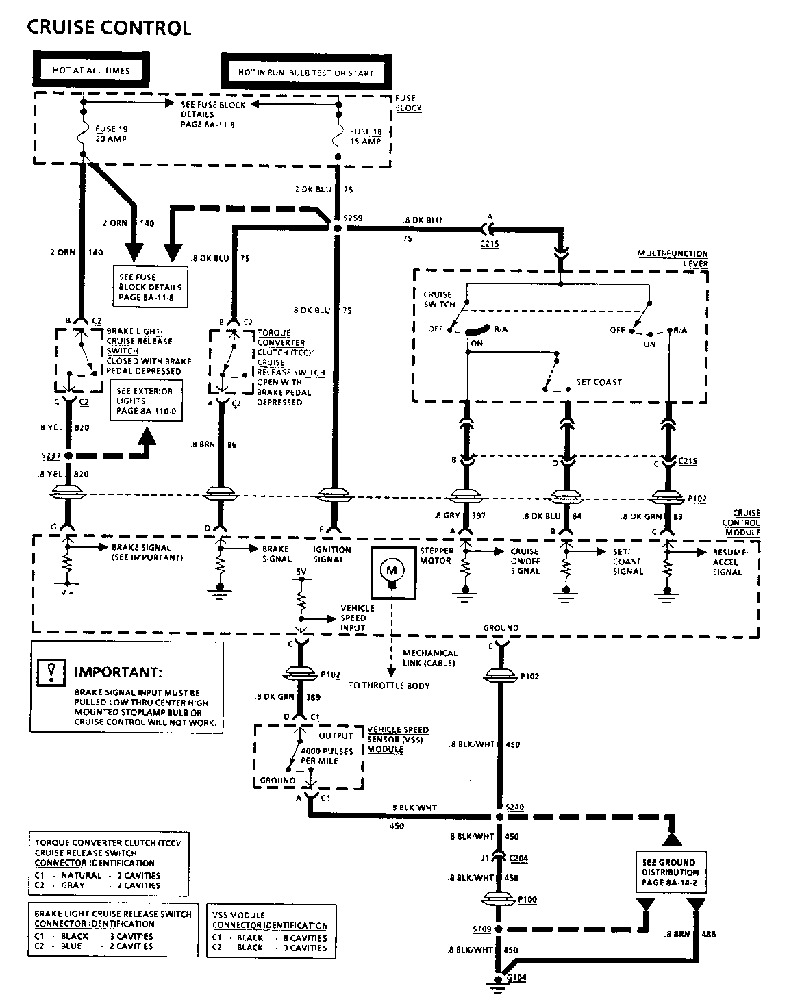
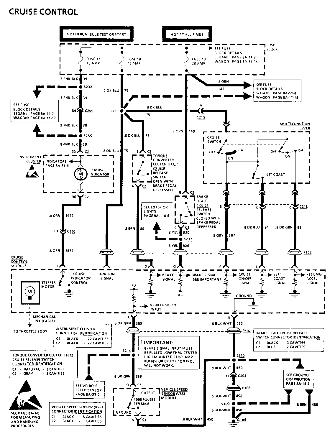
1992 "B" cars (for Buick only, use the following: 1992 Roadmaster Sedans {starting with VIN NR421429} and 1992 Roadmaster Station Wagons) were built with a cruise module that has to have the brake signal input pulled low at terminal "G" for cruise control to function. This is accomplished by a small amount of current flowing from the cruise module, through circuit 820, to the centre High Mount Stop Lamp (CHMSL) bulb to ground. When the brakes are applied and the brake switch closes, the cruise module and circuit 820 receive BATT voltage. This allows the CHMSL bulb to illuminate and the cruise module to sense that the brakes are applied.
Please replace pages 8A-34-0 and 8A-34-1 of the 1992 Service Manual with the attached.
The brake switch mechanization, as shown on page 8A-34-0, has been re-drawn to show it in the "normally open" state. Step 2 of the troubleshooting hints, on page 8A-34-1, includes checking the CHMSL in the event cruise control is disabled.
FOR BUICK ONLY:
For 1992 Roadmaster Sedans built before VIN NR421429, use the 1992 Preliminary Roadmaster Service Manual for Electrical Diagnosis and Repair.
COMPONENT LOCATION 201-PG FIG. CONN --------------------- -------------------------------------------------- Brake Light/Cruise Release Switch ....... Attached to Brake Pedal Bracket (Bottom Switch) .... 14 ... 24 Cruise Control Module .... Fastened to LH Front Wheelhouse.... 40...61 202-6 Fuse Block .............. Mounted to LH I/P, accessible with LH Front Door open ............................... 14 ... 24 Multi-Function Lever .... LH side of Steering Column .............. 18 ... 29 Torque Converter Clutch (TCC)/Cruise Release Switch........ Attached to Brake Pedal Bracket (Top Switch).......14 ... 24 Vehicle Speed Sensor (VSS) Module........LH I/P, top of Convenience Center .......... 14 ... 24 202-10 C204 (37 cavities) .......Body Harn to Engine Harn, behind RH I/P, between Blower Motor and I/P Compartment.....23...37..202-2 C215 (4 cavities) ....... Body Harn to Steering Column Harn, on Lower Steering Column to Cruise Control Switch .................17...27..202-3 G104 ................... RH Rear Cylinder Head below Exhaust Manifold...... ..................9, 10...16,18 P100.....................RH I/P, forward of B lower Motor ...........6.... 13 P102 .................... Visible from Engine Compartment, behind LH Wheelhouse ........................... 40 ... 61 S109 .................... Engine Harn, approx 12 cm from A/C Pressure Cycling Switch Conn Breakout S237 .................... Body Harn, approx 12 cm from C101 Breakout S240 .................... Body Harn, approx 4 cm from Turn/Hazard Switch Conn Breakout S259 .................... Body Harn, approx 15 cm from Fuse Block Breakout
TROUBLESHOOTING HINTS
(Perform before beginning System Diagnosis)
1. Check that Cruise Control Module Linkage is connected and moving freely.
2. Check Cruise Cable Adjustment. See SECTION 9B.
o Make sure that Center High Mounted Stoplamp is working. If inoperative, Cruise Module will be disabled.
o Refer to System Diagnosis.
SYSTEM DIAGNOSIS
o Perform the System Check and refer to the Symptom Table for the appropriate diagnostic procedure(s).
o If speedometer is inoperative, refer to "Vehicle Speed Sensor," page 8A-33-2.
SYSTEM CHECK ====================== ACTION NORMAL RESULTS -------------------------------------- --------------------------------- [1] o Drive vehicle above 25 mph. Vehicle maintains set speed. o Cruise Switch to "ON." o Depress Set Switch once and release. o Remove foot from accelerator pedal.
[2] o Depress and hold Set Switch until Vehicle decelerates and maintains vehicle speed a new lower set speed, if speed decreases by 4 to 5 mph. is above 25 mph. o Release Set Switch.
COMPONENT LOCATION 201-PG FIG. CONN -------------------- ------------------------------------------------- Brake Light/Cruise
Release Switch...........Attached to Brake Pedal Bracket (Bottom Switch) ...........................11...19
Cruise Control Module .... Fastened to LH Front Wheelhouse ..................32 ... 49..202-6
Fuse Block .............. Mounted to LH I/P accessible with LH Front Door open .....................................11 ... 19
Multi-Function Lever .... LH side of Steering Column................14.....23
Torque Converter Clutch (TCC)/Cruise Release Switch................. Attached to Brake Pedal Bracket (Top Switch) ..........................11..19 Vehicle Speed Sensor (VSS) Module.......LH I/P, top of Convenience Center........11...19...202-10 C204 (37 cavities)........Body Harn to Engine Harn, behind RH I/P, between Blower Motor and I/P Compartment ...19...31..202-2 C215 (4 cavities) .....Body Harn to Steering Column Harn, on Lower Steering Column, to Cruise Control Switch .........................15..24..202-3 G104 ..............RH Rear Cylinder Head, below Exhaust Manifold.....8 ...15 P100...............RH I/P, forward of Blower Motor.................. 6... 13 P102...............Visible from Engine Compartment, behind LH Wheelhouse....................................32...49 S109 ..............Engine Harn, approx 12 cm from A/C Pressure Cycling Switch conn breakout S237 ..............Body Harn, approx 12 cm from C101 Breakout S240 ..............Body Harn, approx 4 cm from Turn/Hazard Switch Conn Breakout S259 ..............Body Harn, approx 15 cm from Fuse Block Breakout
TROUBLESHOOTING HINTS
(Perform before beginning System Diagnosis)
1. Check that Cruise Control Module Linkage is connected and moving freely. 2. Check Cruise Cable Adjustment. See SECTION 9B.
o Make sure that Center High Mounted Stoplamp is working. If inoperative, Cruise Module will be disabled. o Refer to System Diagnosis.
SYSTEM DIAGNOSIS
o Perform the System Check and refer to the Symptom Table for the appropriate diagnostic procedures.
o If speedometer is inoperative, refer to "Vehicle Speed Sensor" page 8A-33-2.
SYSTEM CHECK ============ ACTION NORMAL RESULTS -------------------------------- -------------------------------- [1] o Drive vehicle above 25 mph. Vehicle maintains set speed. o Cruise Switch to "ON". o Depress Set Switch once and release. o Remove foot from accelerator pedal.
[2] o Depress and hold Set Switch until Vehicle decelerates and maintains vehicle speed decreases by a new lower set speed, if speed 4 to 5 mph. is above 25 mph. o Release Set Switch.
[3] o Depress and hold R/A Switch until Vehicle accelerates and maintains vehicle speed increases by 4 to 5 mph. a new higher set speed. o Release R/A Switch.
COMPONENT LOCATION 201 PG FIG. CONN
Brake Light/Cruise Release Switch ......... Attached to Brake Pedal Bracket (Bottom Switch) .... 11 ... 19 Cruise Control Module .... Fastened to LH Front Wheelhouse .................. .....35 ... 54........202-6 Fuse Block .............. Mounted to LH I/P. accessible with LH Front Dooropen ..................... 11 ... 19 Instrument Cluster ....... LH I/P Multi-Function Lever .... LH side of Steering Column.... 14 ... 23 Torque Converter Clutch (TCC)/Cruise Release Switch .................Attached to Brake Pedal Bracket (Top Switch) ........11... 19 Vehicle Speed Sensor (VSS)
Module ..........LH I/P, top of Convenience Center.....11....19......202-10
C200 (56 cavities).......Body Harn to I/P Harn, bolted above Accelerator Pedal........................13 ...21......202-0
C204 (37 eavities).......Body Harn to Engine Harn, behind RH I/P, between Blower Motor and I/P Compartment.... 17...28...202-2 C215 (4 cavities) .......Body Harn to Steering Column Harn, on Lower Steering Column, to Cruise Control Switch...15...24......202-3 G104............. RH Rear Cylinder Head, below Exhaust Manifold.....8.... 15 P100.............RH I/P, forward of Blower Motor.................. 6 .... 13 P102 ............Visible from Engine Compartment behind LH Wheelhouse .................................. 34 ... 54 S109 ............Engine Harn, approx 12 cm from A/C Pressure Cycling Switch Conn Breakout S214 ............Body Harn, approx 18 cm from P102 in Passenger Compartment S232 ............Body Harn, approx 10 cm from Fuse Block Breakout S237 ............Body Harn, approx 12 cm from C101 Breakout S240 ..........Body Harn, approx 4 cm from Turn/Hazard Switch Conn Breakout S255 ..........I/P Harn, approx 8 cm from C200 Breakout S259 ......... Body Harn, approx 15 cm from Fuse Block Breakout
TROUBLESHOOTING HINTS
(Perform before beginning System Diagnosis)
1. Check that Cruise Control Module Linkage is connected and moving freely. 2. Check Cruise Cable Adjustment. See SECTION 9B. o Make sure that Center High Mounted Stoplamp is working. If inoperative, Cruise Module will be disabled. o Refer to System Diagnosis.
SYSTEM DIAGNOSIS
o Perform the System Check and refer to the Symptom Table for the appropriate diagnostic procedure(s). o If speedometer is inoperative, refer to "Vehicle Speed Sensor," page 8A-33-2.


General Motors bulletins are intended for use by professional technicians, not a "do-it-yourselfer". They are written to inform those technicians of conditions that may occur on some vehicles, or to provide information that could assist in the proper service of a vehicle. Properly trained technicians have the equipment, tools, safety instructions and know-how to do a job properly and safely. If a condition is described, do not assume that the bulletin applies to your vehicle, or that your vehicle will have that condition. See a General Motors dealer servicing your brand of General Motors vehicle for information on whether your vehicle may benefit from the information.
