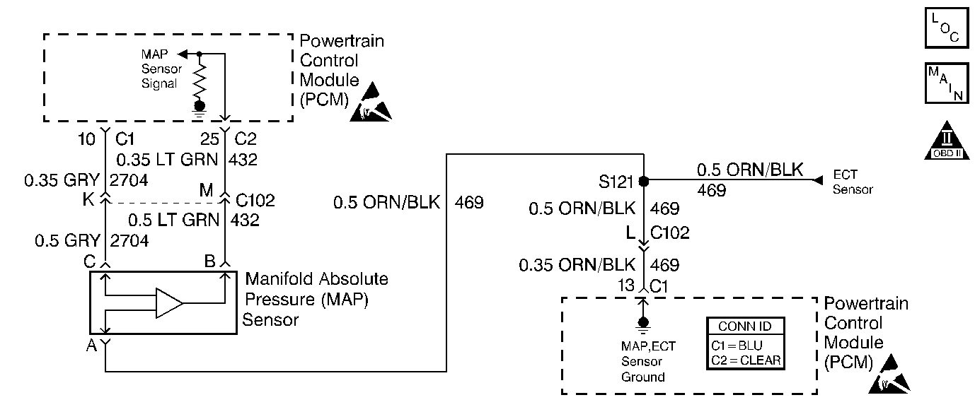
Circuit Description
The manifold absolute pressure (MAP) sensor responds to changes in intake manifold pressure (vacuum). The MAP sensor signal voltage to the Powertrain Control Module (PCM) varies from below 2 volts at idle (high vacuum) to above 4 volts with the key ON, engine not running or at wide open throttle (WOT) (low vacuum). The MAP sensor is used to determine manifold pressure changes while the EGR flow test diagnostic is being run, refer to DTC P0401 Exhaust Gas Recirculation (EGR) Flow Insufficient . Also to update the barometric pressure reading (BARO), as an enabling factor for other diagnostics. The PCM monitors the MAP signals for voltages outside the normal range of the MAP sensor. If the PCM detects a MAP signal voltage that is intermittently low, DTC P1107 will set.
Conditions for Running the DTC
| • | No TP sensor DTCs are present. |
| • | The ignition is ON. |
| • | Throttle angle is steady above 0 percent if engine speed is less than 1000 RPM. |
| • | Throttle angle is steady above 10 percent if engine speed is more than 1000 RPM. |
Conditions for Setting the DTC
The MAP sensor intermittently indicates a voltage below 0.1 volt.
Action Taken When the DTC Sets
The PCM stores conditions which were present when the DTC set as Failure Records only. This information will not be stored as Freeze Frame Records.
Conditions for Clearing the MIL/DTC
| • | The DTC becomes history when the conditions for setting the DTC are no longer present. |
| • | The history DTC clears after 40 malfunction free warm-up cycles. |
| • | The PCM receives a clear code command from the scan tool. |
Diagnostic Aids
Inspect for the following conditions:
| • | Poor connection at the PCM or MAP sensor--Inspect PCM harness connectors: |
| - | Backed out terminals |
| - | Improper mating |
| - | Broken locks |
| - | Improperly formed or damaged terminals |
| - | Poor terminal to wire connection |
| • | Damaged harness--Inspect the wiring harness for damage. If the harness appears to be OK, observe the MAP display on the scan tool while moving connectors and wiring harnesses related to the sensor. A change in the display will indicate the location of the malfunction. |
If the DTC cannot be duplicated and is determined to be intermittent, reviewing the Failure Records can be useful in determining when the DTC was last set. Also refer to Testing for Intermittent Conditions and Poor Connections in Wiring Systems.
Step | Action | Values | Yes | No |
|---|---|---|---|---|
1 | Did you perform the Powertrain On-Board Diagnostic (OBD) System Check? | -- | ||
2 | Is DTC P0107 also set? | -- | Go to DTC P0107 Manifold Absolute Pressure (MAP) Sensor Circuit Low Voltage | |
3 | Is DTC P1122 also set? | -- | ||
4 | Inspect for poor connections at the harness connector of the MAP sensor. Refer to Testing for Intermittent Conditions and Poor Connections and Connector Repairs in Wiring Systems. Did you find and correct the condition? | -- | ||
5 | Inspect the 5 volt reference A circuit of the MAP sensor for a poor connection at the PCM. Refer to Testing for Intermittent Conditions and Poor Connections and Connector Repairs in Wiring Systems. Did you find and correct the condition? | -- | ||
6 | Inspect the signal circuit of the MAP sensor for a poor connection at the PCM. Refer to Testing for Intermittent Conditions and Poor Connections and Connector Repairs in Wiring Systems. Did you find and correct the condition? | -- | ||
7 | Test the 5 volt reference A circuit of the MAP sensor for an intermittent open or short to ground. Refer to Circuit Testing and Wiring Repairs in Wiring Systems. Did you find and correct the condition? | -- | ||
8 | Test the signal circuit of the MAP sensor for an intermittent open or short to ground. Refer to Circuit Testing and Wiring Repairs in Wiring Systems. Did you find and correct the condition? | -- | Go to Diagnostic Aids | |
9 |
Does the DTC reset? | -- | System OK |
