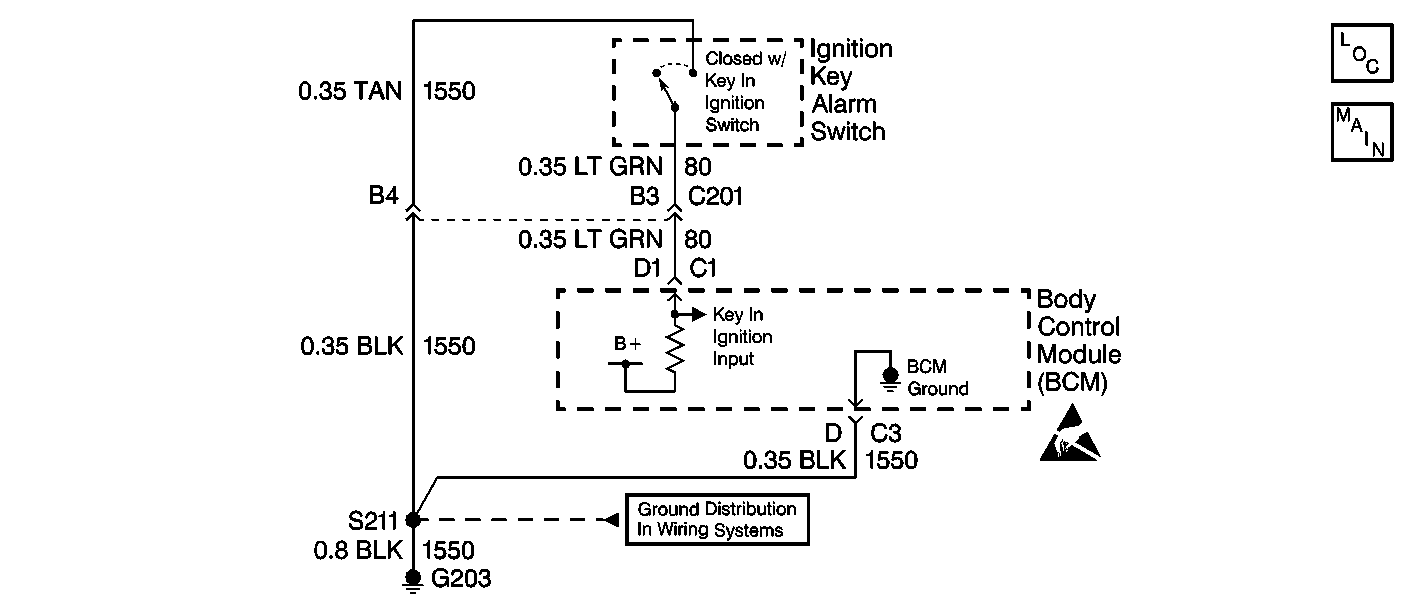
Circuit Description
The BCM interfaces with the key-in-ignition switch. The key-in-ignition switch grounds circuit 80 when the key is fully inserted in the ignition switch. The key-in-ignition switch opens when key is removed from the ignition switch. The BCM uses this input for the operation of the key in the ignition reminder, exit illumination, and lockout prevention. The key-in-ignition switch receives ground through circuit 1550.
Conditions for Setting the DTC
| • | The BCM does not detect a ground signal in circuit 80 when the BCM is detecting voltage in circuit 1550. |
| • | All conditions must be present for more than 0.3 seconds. |
Action Taken When the DTC Sets
The BCM stores DTC B2961 in memory.
Conditions for Clearing the DTC
| • | The BCM receives a key in ground signal (circuit 80) when the ignition switch is not off, then the BCM changes the DTC status from current to history. |
| • | A history DTC will clear after 100 consecutive ignition cycles if the condition for the fault is no longer present. |
| • | Using a scan tool |
Diagnostic Aids
| • | The following conditions may cause an intermittent malfunction to occur: |
| • | An intermittent open or short to ground in circuit 80 |
| • | An intermittent open in circuit 1550 |
| • | Poor connections at the BCM or the key-in-ignition switch |
| • | An intermittent open in G203 |
| • | A faulty ignition switch |
| • | The BCM is open internally. |
| • | DTC P1626 will set in the powertrain control module (PCM) when the ignition switch is on with the body control module (BCM) disconnected. When BCM diagnostics and repairs are completed, refer to Powertrain On Board Diagnostic (OBD) System Check in Engine Controls - 2.5L (LB8) and 3.0L (L46). |
Test Description
The numbers below refer to the step numbers on the diagnostic table.
-
This step determines whether circuit 80 or circuit 1550 is open, or the ignition switch is faulty (contacts always open).
-
This step checks for either a short to ground in circuit 80 or a faulty ignition switch (contacts always closed).
-
This step determines whether the malfunction is intermittent or the BCM is faulty.
-
This step checks for an open in circuit 1550.
-
This step checks for either an open in circuit 80 or a faulty ignition switch.
-
This step checks for either a short to ground in circuit 80 or a faulty ignition switch.
Step | Action | Value(s) | Yes | No |
|---|---|---|---|---|
1 | Was the BCM Diagnostic System Check performed? | -- | Go to Step 2 | Go to Diagnostic System Check - Body Control System in Body Control System |
2 | Inspect for BCM current DTCs. Refer to Diagnostic Trouble Code (DTC) Displaying . Is BCM DTC B0608 also set as a current DTC? | -- | Go to DTC B0608 Power Moding Error in Body Control System | Go to Step 3 |
Is the resistance measured less than the specified value? | 50 ohms | Go to Step 4 | Go to Step 6 | |
Is the resistance measured equal to the specified value? | ∞ | Go to Step 5 | Go to Step 8 | |
Does DTC B2961 reset as a current DTC? | -- | Go to Step 13 | Go to Step 14 | |
Is the test light on? | -- | Go to Step 7 | Go to Step 9 | |
Using a DMM, measure the resistance between the BCM harness connector C1 terminal D1 and the ignition switch harness circuit 80. Is the resistance measured less than the specified value? | 2 ohms | Go to Step 10 | Go to Step 11 | |
Is the resistance measured equal to the specified value? | ∞ | Go to Step 10 | Go to Step 12 | |
9 | Repair a poor connection or an open in circuit 1550. Is the repair complete? | -- | Go to Step 15 | -- |
10 | Replace the ignition switch. Refer to Ignition and Key Alarm Switch Assembly - Disassemble - Off Vehicle in Steering Wheel and Column - Tilt. Is the repair complete? | -- | Go to Step 15 | -- |
11 | Repair a poor connection or an open in circuit 80. Is the repair complete? | -- | Go to Step 15 | -- |
12 | Repair a short to ground in circuit 80. Is the repair complete? | -- | Go to Step 15 | -- |
13 |
Is the repair complete? | -- | Go to Step 15 | -- |
14 | The malfunction is not present at this time. Refer to Diagnostic Aids for additional information regarding this DTC. Is the repair complete? | -- | Go to Step 15 | -- |
15 |
Are there any BCM current DTCs set? | -- | Go to Diagnostic System Check - Body Control System in Body Control System | System OK |
