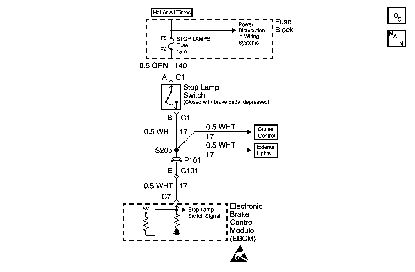
Circuit Description
The EBCM sources 5 volts on the stoplamp signal circuit. The voltage is supplied a ground path through the stoplamp bulbs. This DTC sets when the path to ground is open or has high resistance.
Conditions for Running the DTC
This DTC can set at anytime that the EBCM is powered.
Conditions for Setting the DTC
| • | The stoplamp switch signal voltage is between 2.2 volts and 5.0 volts. |
| • | The above condition is present for greater than 2.0 seconds. |
Action Taken When the DTC Sets
| • | TCS is disabled |
| • | Traction Control indicator is turned on |
| • | ABS remains functional |
Conditions for Clearing the DTC
| • | Condition for DTC is no longer present and scan tool clear DTC function is used. |
| • | 100 ignition cycles have passed with no DTCs detected. |
Diagnostic Aids
| • | Possible causes: |
| - | Stoplamp switch input circuit open. |
| - | All stoplamps open. |
| - | Open stoplamp ground. |
| - | Circuit has a wiring problem, terminal corrosion, or poor connections. |
| • | It is very important that a thorough inspection of the wiring and connectors be performed. Failure to carefully and fully inspect wiring and connectors may result in misdiagnosis, causing part replacement with reappearance of the malfunction. |
| • | If an intermittent malfunction exists refer to Testing for Intermittent Conditions and Poor Connections in Wiring Systems. |
Test Description
The number(s) below refer to the step number(s) on the diagnostic table.
-
This DTC detects an open stop lamp signal circuit from the stoplamp side of the IP Accessory Wiring Junction Block to the EBCM.
-
The EBCM sources 5 volts on the stoplamp signal circuit. This small voltage has a ground path through the stoplamp bulbs. This DTC sets if the path to ground is open.
Step | Action | Value(s) | Yes | No |
|---|---|---|---|---|
1 | Did you perform the ABS Diagnostic System Check? | -- | Go to Step 2 | |
2 |
Does the Brake Switch Status parameter display Applied? | -- | Go to Step 4 | Go to Step 3 |
Test the signal circuit of the stoplamp switch for an open. Refer to Circuit Testing and Wiring Repairs in Wiring Systems. Did you find and correct the condition? | -- | Go to Step 9 | Go to Step 7 | |
Press the brake pedal. Are all of the stoplamps OFF? | -- | Go to Step 5 | Go to Diagnostic Aids | |
5 | Test the feed circuit of the stoplamps for an open or high resistance. Did you find and correct the condition? | -- | Go to Step 9 | Go to Step 6 |
6 | Test the ground circuit for the stoplamps for an open or high resistance. Did you find and correct the condition? | -- | Go to Step 9 | Go to Diagnostic Aids |
7 | Inspect for poor connections at the harness connector of the EBCM. Refer to Testing for Intermittent Conditions and Poor Connections and Connector Repairs in Wiring Systems. Did you find and correct the condition? | -- | Go to Step 9 | Go to Step 8 |
8 | Replace the EBCM. Refer to Electronic Brake Control Module Replacement . Did you complete the replacement? | -- | Go to Step 9 | -- |
9 |
Does the DTC reset? | -- | Go to Step 2 | System OK |
