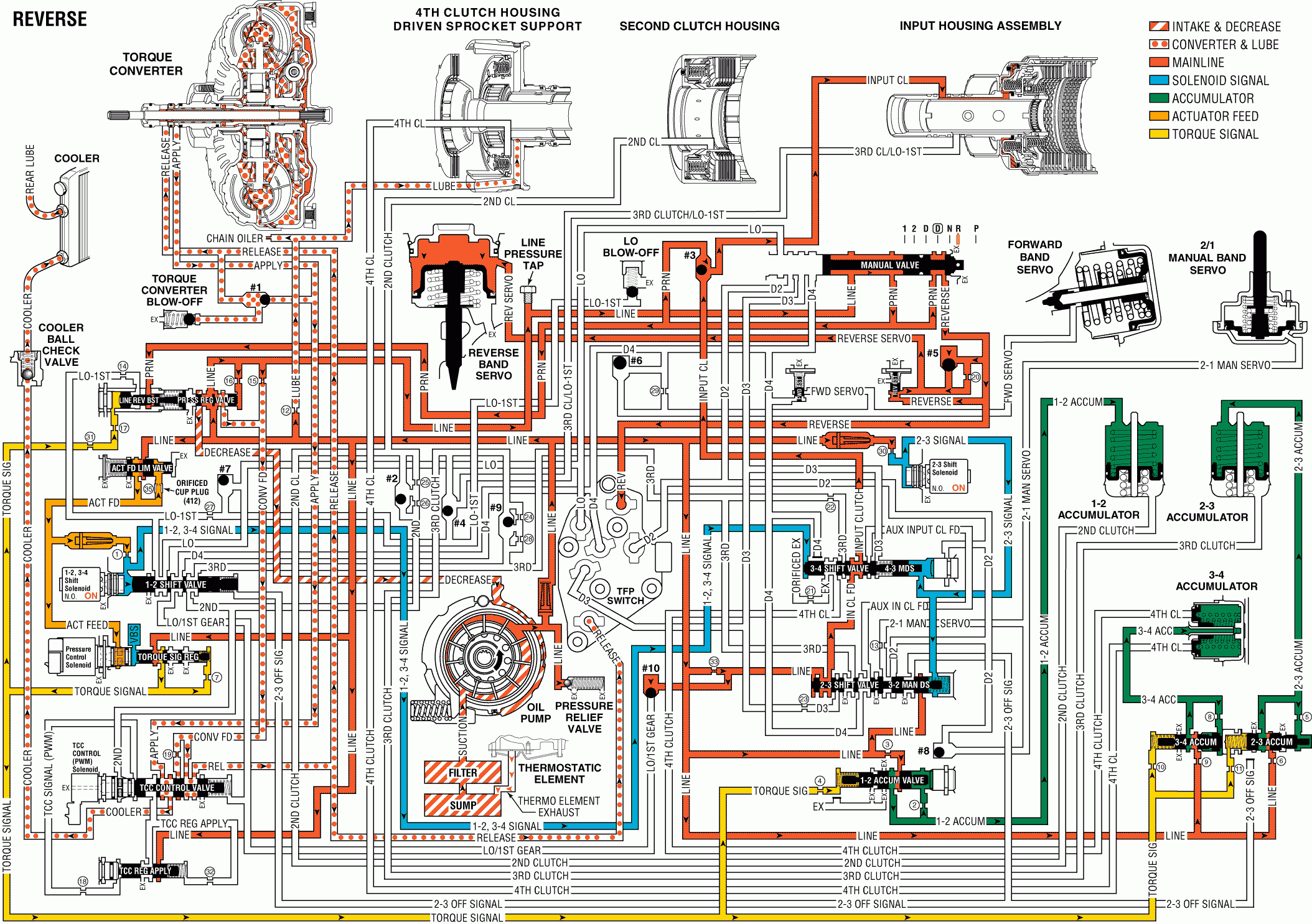
When the gear selector lever is moved to the REVERSE (R) position (from the PARK position) the following changes occur in the transmission's hydraulic and electrical systems.
Pressure Regulator Valve (313)
Increases (or decreases) in line pressure is primarily influenced by changes in the throttle position as a result of the changing operating conditions of the vehicle.
Manual Valve (404)
Is moved manually to the right through the gear selector lever and allows line pressure to enter the reverse fluid passage through the PRN fluid passage.
Number 5 Ball Check Valve (373)
Located in the control valve body, (300), it blocks the reverse servo feed passage forcing reverse fluid through an orifice in the spacer plate (370) into the reverse servo passage. When the manual valve (404) is moved out of reverse, the ball check valve unseats allowing reverse servo fluid to exhaust through the ball seat instead of through the orifice.
Reverse Boost Valve (367A)
Opens under hard acceleration (high line pressure/high throttle position) to allow reverse fluid to by-pass the feed orifice and enter the reverse servo passage. This provides for a quick fill of the servo passage and quick apply of the reverse band to prevent band slippage during abusive shifts from PARK or NEUTRAL to REVERSE.
Transmission Fluid Pressure (TFP) Manual Valve Position Switch Assembly (34)
Reverse fluid is routed to the TFP manual valve position switch. The TFP manual valve position switch signals the PCM that the transmission is in REVERSE.
Reverse Servo Assembly (39-40)
Applies the reverse band (615) in response to reverse servo fluid pressure feeding into the servo cover (40) side of the reverse servo piston (44).
Reverse Band Assembly (615)
Wraps around the second clutch housing (617) and holds the input carrier (672), through the reverse reaction drum (669), allowing the vehicle to move in reverse.
Input Clutch
Remains applied from PARK to REVERSE and becomes effective as the reverse band applies. The input sprag holds at this time.
Pressure Regulator Valve (313) (Torque Converter/Cooler and Lube Circuits)
Line pressure at the valve enters the converter feed circuit which is then routed to the TCC control valve.
TCC Control Valve (335)
Spring pressure holds the valve in the released position. Converter feed fluid is directed to the release circuit. Release fluid seats #1 ball check valve and feeds the TCC blow-off. Release fluid feeds the TCC on the cover side of the pressure plate, exits the TCC through the apply circuit, then feeds the cooler circuit at the TCC control valve. Cooler fluid passes through the ball check valve, through the cooler, then returns to the transmission and feeds the rear lube circuit. A front lube circuit is fed from orificed line pressure.
Reverse

