Circuit Description
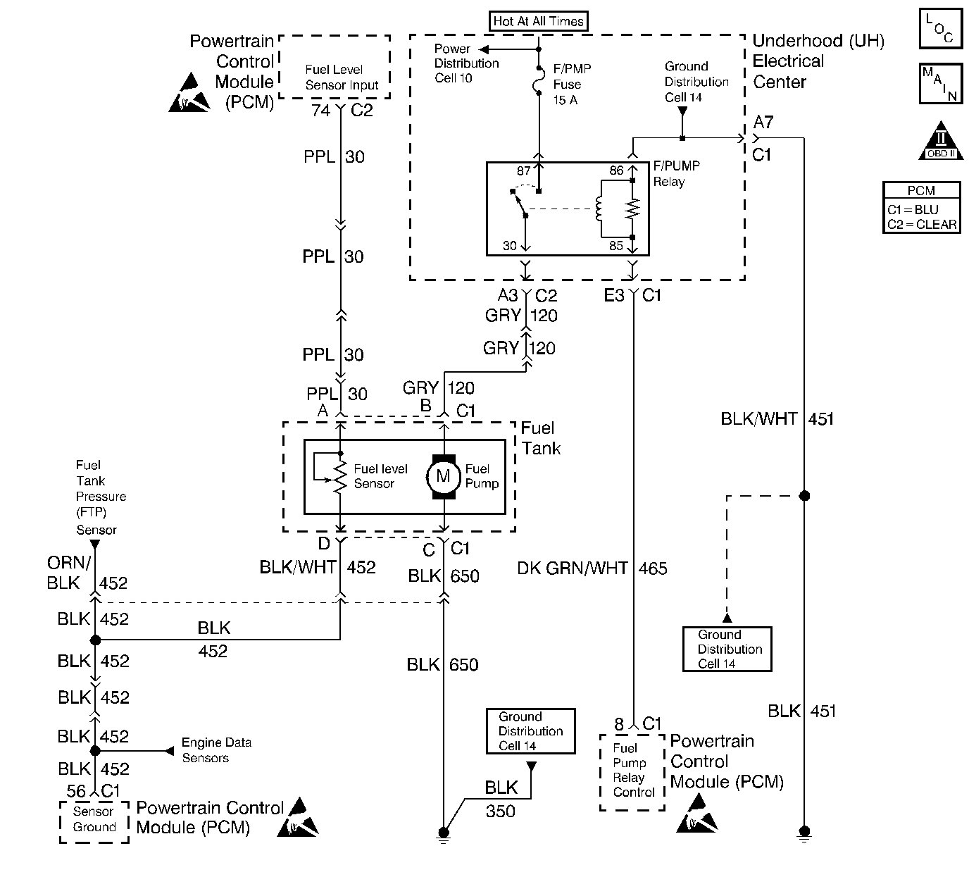
When the ignition switch is first turned on, the PCM energizes the fuel pump relay which applies power to the in-tank fuel pump. The fuel pump relay will remain on as long as the engine is running or cranking and the PCM is receiving reference pulses. If no reference pulses are present, the PCM de-energizes the fuel pump relay within 2 seconds after the ignition is turned on or the engine is stopped.
The fuel pump delivers fuel to the fuel rail and injectors, then to the fuel pressure regulator. The fuel pressure regulator controls fuel pressure by allowing excess fuel to be returned to the fuel tank.
Diagnostic Aids
An intermittent may be caused by a poor connection, rubbed through wire insulation or a wire broken inside the insulation. Check for a poor connection or damaged harness. Inspect the PCM harness and connectors for the following items:
| • | Improper mating. |
| • | Broken locks. |
| • | Improperly formed or damaged terminals. |
| • | Poor terminal to wire connections. |
| • | Damaged harnesses. |
Test Description
Number(s) below refer to the Step number(s) on the Diagnostic Chart:
-
Verifies that the fuel pump feed circuit is OK between the fuel pump relay and the fuel pump, and that the fuel pump can deliver adequate pressure to the fuel rail.
-
Checks the ignition feed circuit to the fuel pump relay.
-
Verifies that the fuel pump relay driver circuit and the PCM are capable of controlling the fuel pump relay.
-
Checks the fuel pump driver circuit for a short to ground.
-
Checks the fuel pump driver circuit for an open.
-
If the fuel pump is operating but incorrect pressure is noted, the fuel pump wiring is OK and Fuel System Pressure Test should be used for diagnosis.
-
Checks the fuel pump feed circuit between the fuel pump relay and the fuel pump. Also checks the fuel pump ground circuit.
-
Determines whether the problem is being caused by an open in the fuel pump feed circuit or the fuel pump ground circuit.
-
This vehicle is equipped with a PCM which utilizes an Electrically Erasable Programmable Read Only Memory (EEPROM). When the PCM is being replaced, the new PCM must be programmed. Refer to Powertrain Control Module Replacement/Programming .
Step | Action | Value(s) | Yes | No | ||||
|---|---|---|---|---|---|---|---|---|
1 | Was the Powertrain On Board Diagnostic (OBD) System Check performed? | -- | ||||||
2 |
Is the proper fuel pressure indicated? | 284-325 kPa (41-47 psi) | ||||||
3 |
Did the test light turn on for approximately 2 seconds? | -- | ||||||
4 |
Is the test light on? | -- | ||||||
5 | Check the fuel pump system fuse. Is the fuse blown? | -- | ||||||
6 |
Is the test light on? | -- | ||||||
7 |
Is the test light on? | -- | ||||||
8 |
Is the test light on? | -- | ||||||
9 |
Is the test light on? | -- | ||||||
10 |
Was a problem found? | -- | ||||||
11 | Locate and repair short to ground in the battery positive voltage feed to the fuel pump relay. Refer to Repair Procedures in Electrical Diagnosis. Is the action complete? | -- | -- | |||||
12 | Locate and repair open in the battery positive voltage feed to the fuel pump relay. Refer to Repair Procedures in Electrical Diagnosis. Is the action complete? | -- | -- | |||||
13 | Connect the test light between battery positive voltage feed circuit in the fuel pump connector and chassis ground. Is the test light on? | -- | ||||||
14 | Locate and repair open in fuel pump ground circuit. Refer to Repair Procedures in Electrical Diagnosis. Is the action complete? | -- | -- | |||||
15 | Locate and repair open in the battery positive voltage feed circuit to the fuel pump. Refer to Repair Procedures in Electrical Diagnosis. Is the action complete? | -- | -- | |||||
16 | Locate and repair short to chassis/fuel pump ground. Refer to Repair Procedures in Electrical Diagnosis. Is the action complete? | -- | -- | |||||
17 |
Was a problem found? | -- | ||||||
18 | Locate and repair open in ground circuit to the fuel pump relay. Refer to Repair Procedures in Electrical Diagnosis. Is the action complete? | -- | -- | |||||
19 | Replace the fuel pump relay. Is the action complete? | -- | -- | |||||
20 | Replace the fuel pump. Is the action complete? | -- | -- | |||||
21 | Replace the PCM. Important: : Replacement PCM must be programmed. Refer to Powertrain Control Module Replacement/Programming . Is the action complete? | -- | -- | |||||
22 |
Is the proper fuel pressure indicated? | 284-325 kPa (41-47 psi) | System OK |
