For 1990-2009 cars only
Removal Procedure
- Disconnect the negative battery cable. Refer to Battery Negative Cable Disconnection and Connection in Engine Electrical.
- Remove the outer trim cover. Refer to Instrument Panel Outer Trim Cover Replacement in Instrument Panel, Gages and Console.
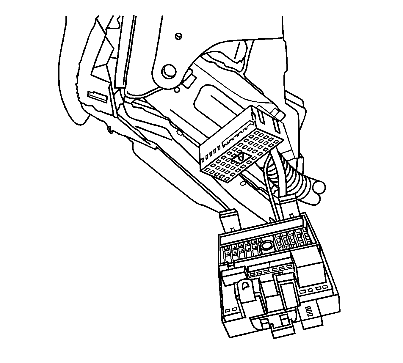
- Disconnect the body wiring harness from the accessory wiring junction block. Pull the harness away from the block for access.
- Remove the instrument panel (I/P) compartment. Refer to Instrument Panel Compartment Replacement in Instrument Panel, Gages and Console.
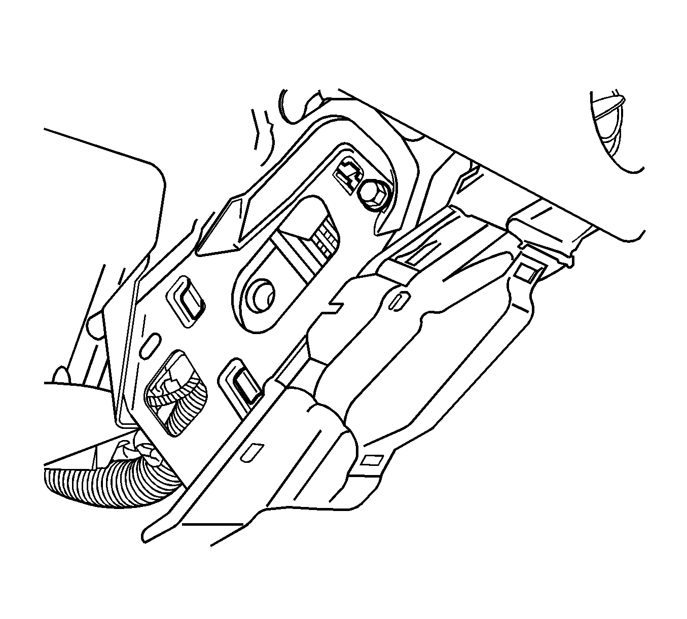
- Remove the junction block bolt.
- Disengage the junction block tabs from the passenger knee bolster. Pull the junction block away from the I/P.
- Remove the junction block.


Installation Procedure
- Seat the bottom junction block tabs and snap the top of the junction block to the passenger knee bolster.
- Install the junction block bolt.
- Connect the body wiring harnesses to the junction block.
- Install the I/P compartment. Refer to Instrument Panel Compartment Replacement in Instrument Panel, Gages and Console.
- Install the outer trim cover. Refer to Instrument Panel Outer Trim Cover Replacement in Instrument Panel, Gages and Console.
- Connect the negative battery cable. Refer to Battery Negative Cable Disconnection and Connection in Engine Electrical.

Notice: Refer to Fastener Notice in the Preface section.

Tighten
Tighten the junction block bolt to 10 N·m (89 lb in).
Tighten
Tighten the connector bolt to 2.5 N·m (22 lb in).
